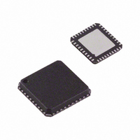
AD8339ACPZ Analog Devices Inc, AD8339ACPZ Datasheet - Page 21

AD8339ACPZ
Manufacturer Part Number
AD8339ACPZ
Description
IC I/Q DEMOD QUAD 50MHZ 40-LFCSP
Manufacturer
Analog Devices Inc
Datasheet
1.AD8339ACPZ.pdf
(36 pages)
Specifications of AD8339ACPZ
Function
Demodulator
Lo Frequency
0Hz ~ 200MHz
Rf Frequency
0Hz ~ 50MHz
P1db
14.8dBm
Gain
-1.3dB
Noise Figure
11.5dB
Current - Supply
35mA
Voltage - Supply
4.5 V ~ 5.5 V
Package / Case
40-VFQFN, 40-CSP, Exposed Pad
Frequency Range
DC To 50MHz
Rf Type
Quadrature
Supply Voltage Range
± 4.5V To ± 5.5V
Rf Ic Case Style
LFCSP
No. Of Pins
40
Operating Temperature Range
-40°C To +85°C
Lead Free Status / RoHS Status
Lead free / RoHS Compliant
For Use With
AD8339-EVALZ - BOARD EVAL AD8339 I/Q DEMOD
Lead Free Status / RoHS Status
Lead free / RoHS Compliant, Lead free / RoHS Compliant
Available stocks
Company
Part Number
Manufacturer
Quantity
Price
Company:
Part Number:
AD8339ACPZ
Manufacturer:
Analog Devices Inc
Quantity:
135
Combining Phase Compensation and Analog
Beamforming
Modern ultrasound machines used for medical applications
employ an array of receivers for beamforming, with typical CW
Doppler array sizes of up to 64 receiver channels that are phase
shifted and summed together to extract coherent information.
When used in multiples, the desired signals from each of the
channels can be summed to yield a larger signal (increased by a
factor N, where N is the number of channels), and the noise is
increased by the square root of the number of channels. This
technique enhances the signal-to-noise performance of the
machine. The critical elements in a beamformer design are the
means to align the incoming signals in the time domain and the
means to sum the individual signals into a composite whole.
In traditional analog beamformers incorporating Doppler, a
V-to-I converter per channel and a crosspoint switch precede
passive delay lines used as a combined phase shifter and
summing circuit. The system operates at the carrier frequency
(RF) through the delay line, which also sums the signals from
the various channels, and then the combined signal is down-
converted by a very large dynamic range I/Q demodulator.
The resultant I and Q signals are filtered and then sampled by
two high resolution analog-to-digital converters. The sampled
signals are processed to extract the relevant Doppler information.
Alternatively, the RF signal can be processed by downconversion
on each channel individually, phase shifting the downconverted
signal, and then combining all channels. The
AD8339 implement this architecture. The downconversion is done
by an I/Q demodulator on each channel, and the summed current
output is the same as in the delay line approach. The subsequent
filters after the I-to-V conversion and the ADCs are similar.
45° EACH WITH
ARE DELAYED
EACH OTHER
RESPECT TO
4 US WAVES
135°
90°
45°
Figure 54. Simplified Example of the AD8339 Phase Shifter
AD8333
CONVERT US TO
0°
ELEMENTS TE1
THROUGH TE4
TRANSDUCER
ELECTRICAL
SIGNALS
and the
E1
E2
E3
E4
Rev. A | Page 21 of 36
19dB
LNA
19dB
LNA
19dB
LNA
19dB
LNA
AD8334
The AD8339 integrates the phase shifter, frequency conversion,
and I/Q demodulation into a single package and directly yields
the baseband signal. Figure 54 is a simplified diagram showing
the concept for all four channels. The ultrasound wave (US wave)
is received by four transducer elements, TE1 through TE4, in an
ultrasound probe and generates signals E1 through E4. In this
example, the phase at TE1 leads the phase at TE2 by 45°.
Channel Summing
Figure 55 shows a 16-channel beamformer using AD8339s,
AD8021s, and an AD797. The number of channels summed is
limited by the current drive capability of the amplifier used to
implement the active low-pass filter and current-to-voltage
converter. An
In an ultrasound application, the instantaneous phase difference
between echo signals is influenced by the transducer-element
spacing, the wavelength (λ), the speed of sound in the media, the
angle of incidence of the probe to the target, and other factors.
In Figure 54, the signals E1 through E4 are amplified 19 dB by
the low noise amplifiers in the AD8334; for lower power portable
ultrasound applications, the
AD8334 for the lowest power per channel. For optimum signal-
to-noise performance, the output of the LNA is applied directly
to the input of the AD8339. To sum the signals E1 through E4,
E2 is shifted 45° relative to E1 by setting the phase code in
Channel 2 to 0010, E3 is shifted 90° (0100), and E4 is shifted
135° (0110). The phase aligned current signals at the output of
the AD8339 are summed in an I-to-V converter to provide the
combined output signal with a theoretical improvement in
dynamic range of 6 dB for the four channels.
PHASE SET
PHASE SET
PHASE SET
PHASE SET
PHASE BIT
SETTINGS
FOR 135°
FOR 90°
FOR 45°
AD8339
FOR 0°
CH 1
CH 2
CH 3
CH 4
LAG
LAG
LAG
LAG
AD8021
S1 THROUGH S4
ARE NOW IN
S1
S2
S3
S4
PHASE
sums up to 16 AD8339 outputs.
AD8335
S1 + S2 + S3 + S4
SUMMED
OUTPUT
can be used instead of the
AD8339


