HD6417032F20 Renesas Electronics America, HD6417032F20 Datasheet - Page 85
HD6417032F20
Manufacturer Part Number
HD6417032F20
Description
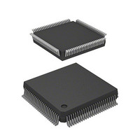
IC SUPERH MPU ROMLESS 112QFP
Manufacturer
Renesas Electronics America
Series
SuperH® SH7030r
Datasheet
1.HD6417034AFI20.pdf
(689 pages)
Specifications of HD6417032F20
Core Processor
SH-1
Core Size
32-Bit
Speed
20MHz
Connectivity
EBI/EMI, SCI
Peripherals
DMA, POR, PWM, WDT
Number Of I /o
32
Program Memory Type
ROMless
Ram Size
4K x 8
Voltage - Supply (vcc/vdd)
4.5 V ~ 5.5 V
Data Converters
A/D 8x10b
Oscillator Type
Internal
Operating Temperature
-20°C ~ 75°C
Package / Case
112-QFP
Lead Free Status / RoHS Status
Contains lead / RoHS non-compliant
Eeprom Size
-
Program Memory Size
-
Available stocks
Company
Part Number
Manufacturer
Quantity
Price
Company:

Part Number:
HD6417032F20
Manufacturer:
HIT
Quantity:
5 510
Company:
Part Number:
HD6417032F20
Manufacturer:
AMCC
Quantity:
5 510
Company:
Part Number:
HD6417032F20
Manufacturer:
Renesas Electronics America
Quantity:
10 000
Part Number:
HD6417032F20
Manufacturer:
HITACHI/日立
Quantity:
20 000
Company:
Part Number:
HD6417032F20V
Manufacturer:
TI
Quantity:
201


4.2.2
When the NMI pin is high, a low input at the RES pin drives the chip into the power-on reset state.
The RES pin should be driven low while the clock pulse generator (CPG) is stopped (or while the
CPG is operating during the oscillation settling time) for at least 20 t
reset. A power-on reset initializes the internal state of the CPU and all registers of the on-chip
supporting modules. For pin states in the power-on reset state, see appendix B, Pin States.
While the NMI pin remains high, if the RES pin is held low for a certain time then driven high in
the power-on state, power-on reset exception handling begins. The CPU then:
1. Reads the start address (initial PC value) from the exception vector table.
2. Reads the initial stack pointer value (SP) from the exception vector table.
3. Clears the vector base register (VBR) to H'00000000, and sets interrupt mask bits I3–I0 in the
4.
A power-on reset must be executed when turning on power.
4.2.3
When the NMI pin is high, a low input at the RES pin drives the chip into the manual reset state.
To ensure that the chip is properly reset, drive the RES pin low for at least 20 t
initializes the internal state of the CPU and all registers of the on-chip supporting modules except
the bus state controller, pin function controller, and I/O ports. Since a manual reset does not affect
the bus state controller, the DRAM refresh control function operates even if the manual reset state
continues for a long time. When a manual reset is performed during the bus cycle, manual reset
exception handling is deferred until the end of the bus cycle. The manual reset thus cannot be used
to abort the bus cycle. For the pin states during the manual reset state, see appendix B, Pin States.
While the NMI pin remains low, if the RES pin is held low for a certain time then driven high in
the manual reset state, manual reset exception handling begins. The CPU carries out the same
operations as for a power-on reset.
status register (SR) to H'F (1111).
Loads the values read from the exception vector table into the PC and SP and starts program
execution.
Power-On Reset
Manual Reset
Rev. 7.00 Jan 31, 2006 page 57 of 658
Section 4 Exception Handling
cyc
to assure that the chip is
cyc
REJ09B0272-0700
. A manual reset
Related parts for HD6417032F20
Image
Part Number
Description
Manufacturer
Datasheet
Request
R

Part Number:
Description:
KIT STARTER FOR M16C/29
Manufacturer:
Renesas Electronics America
Datasheet:

Part Number:
Description:
KIT STARTER FOR R8C/2D
Manufacturer:
Renesas Electronics America
Datasheet:

Part Number:
Description:
R0K33062P STARTER KIT
Manufacturer:
Renesas Electronics America
Datasheet:

Part Number:
Description:
KIT STARTER FOR R8C/23 E8A
Manufacturer:
Renesas Electronics America
Datasheet:

Part Number:
Description:
KIT STARTER FOR R8C/25
Manufacturer:
Renesas Electronics America
Datasheet:

Part Number:
Description:
KIT STARTER H8S2456 SHARPE DSPLY
Manufacturer:
Renesas Electronics America
Datasheet:

Part Number:
Description:
KIT STARTER FOR R8C38C
Manufacturer:
Renesas Electronics America
Datasheet:

Part Number:
Description:
KIT STARTER FOR R8C35C
Manufacturer:
Renesas Electronics America
Datasheet:

Part Number:
Description:
KIT STARTER FOR R8CL3AC+LCD APPS
Manufacturer:
Renesas Electronics America
Datasheet:
Part Number:
Description:
KIT STARTER FOR RX610
Manufacturer:
Renesas Electronics America
Datasheet:

Part Number:
Description:
KIT STARTER FOR R32C/118
Manufacturer:
Renesas Electronics America
Datasheet:

Part Number:
Description:
KIT DEV RSK-R8C/26-29
Manufacturer:
Renesas Electronics America
Datasheet:

Part Number:
Description:
KIT STARTER FOR SH7124
Manufacturer:
Renesas Electronics America
Datasheet:

Part Number:
Description:
KIT STARTER FOR H8SX/1622
Manufacturer:
Renesas Electronics America
Datasheet:

Part Number:
Description:
KIT DEV FOR SH7203
Manufacturer:
Renesas Electronics America
Datasheet: