MC56F8366MFVE Freescale Semiconductor, MC56F8366MFVE Datasheet - Page 178
MC56F8366MFVE
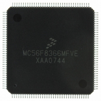
Manufacturer Part Number
MC56F8366MFVE
Description
IC DSP 16BIT 60MHZ 144-LQFP
Manufacturer
Freescale Semiconductor
Series
56F8xxxr
Datasheet
1.MC56F8366VFVE.pdf
(182 pages)
Specifications of MC56F8366MFVE
Core Processor
56800
Core Size
16-Bit
Speed
60MHz
Connectivity
CAN, EBI/EMI, SCI, SPI
Peripherals
POR, PWM, Temp Sensor, WDT
Number Of I /o
62
Program Memory Size
544KB (272K x 16)
Program Memory Type
FLASH
Ram Size
18K x 16
Voltage - Supply (vcc/vdd)
2.25 V ~ 3.6 V
Data Converters
A/D 16x12b
Oscillator Type
External
Operating Temperature
-40°C ~ 125°C
Package / Case
144-LQFP
For Use With
MC56F8367EVME - EVAL BOARD FOR MC56F83X
Lead Free Status / RoHS Status
Lead free / RoHS Compliant
Eeprom Size
-
Available stocks
Company
Part Number
Manufacturer
Quantity
Price
Company:

Part Number:
MC56F8366MFVE
Manufacturer:
Freescale
Quantity:
440
Company:
Part Number:
MC56F8366MFVE
Manufacturer:
Freescale Semiconductor
Quantity:
10 000
Part Number:
MC56F8366MFVE
Manufacturer:
FREESCALE
Quantity:
20 000


Please see www.freescale.com for the most current case outline.
Part 12 Design Considerations
12.1 Thermal Design Considerations
An estimation of the chip junction temperature, T
T
where:
The junction-to-ambient thermal resistance is an industry-standard value that provides a quick and easy
estimation of thermal performance. Unfortunately, there are two values in common usage: the value
determined on a single-layer board and the value obtained on a board with two planes. For packages such
as the PBGA, these values can be different by a factor of two. Which value is closer to the application
depends on the power dissipated by other components on the board. The value obtained on a single-layer
board is appropriate for the tightly packed printed circuit board. The value obtained on the board with the
internal planes is usually appropriate if the board has low-power dissipation and the components are well
separated.
When a heat sink is used, the thermal resistance is expressed as the sum of a junction-to-case thermal
resistance and a case-to-ambient thermal resistance:
R
where:
R
change the case-to-ambient thermal resistance, R
sink, the air flow around the device, the interface material, the mounting arrangement on printed circuit
board, or change the thermal dissipation on the printed circuit board surrounding the device.
To determine the junction temperature of the device in the application when heat sinks are not used, the
Thermal Characterization Parameter (Ψ
measurement of the temperature at the top center of the package case using the following equation:
T
where:
178
T
R
P
R
R
R
T
J
J
D
θJΑ =
θJC
A
T
θJΑ
θJA
θJC
θCA
= T
= T
is device-related and cannot be influenced by the user. The user controls the thermal environment to
= Thermocouple temperature on top of package (
A
T
= Ambient temperature for the package (
= Junction-to-ambient thermal resistance (
= Power dissipation in the package (W)
R
+ (Ψ
+ (R
= Package junction-to-ambient thermal resistance °C/W
= Package junction-to-case thermal resistance °C/W
= Package case-to-ambient thermal resistance °C/W
θJC +
θJΑ
JT
R
x P
θCΑ
x
P
D
D
)
)
56F8366 Technical Data, Rev. 7
JT
) can be used to determine the junction temperature with a
θCA
o
J
C)
o
, can be obtained from the equation:
C/W)
. For instance, the user can change the size of the heat
o
C)
Freescale Semiconductor
Preliminary
Related parts for MC56F8366MFVE
Image
Part Number
Description
Manufacturer
Datasheet
Request
R

Part Number:
Description:
56f8300 16-bit Digital Signal Controllers
Manufacturer:
Freescale Semiconductor, Inc
Datasheet:
Part Number:
Description:
Manufacturer:
Freescale Semiconductor, Inc
Datasheet:
Part Number:
Description:
Manufacturer:
Freescale Semiconductor, Inc
Datasheet:
Part Number:
Description:
Manufacturer:
Freescale Semiconductor, Inc
Datasheet:
Part Number:
Description:
Manufacturer:
Freescale Semiconductor, Inc
Datasheet:
Part Number:
Description:
Manufacturer:
Freescale Semiconductor, Inc
Datasheet:
Part Number:
Description:
Manufacturer:
Freescale Semiconductor, Inc
Datasheet:
Part Number:
Description:
Manufacturer:
Freescale Semiconductor, Inc
Datasheet:
Part Number:
Description:
Manufacturer:
Freescale Semiconductor, Inc
Datasheet:
Part Number:
Description:
Manufacturer:
Freescale Semiconductor, Inc
Datasheet:
Part Number:
Description:
Manufacturer:
Freescale Semiconductor, Inc
Datasheet:
Part Number:
Description:
Manufacturer:
Freescale Semiconductor, Inc
Datasheet:
Part Number:
Description:
Manufacturer:
Freescale Semiconductor, Inc
Datasheet:
Part Number:
Description:
Manufacturer:
Freescale Semiconductor, Inc
Datasheet:
Part Number:
Description:
Manufacturer:
Freescale Semiconductor, Inc
Datasheet: