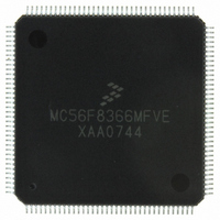
MC56F8366MFVE Freescale Semiconductor, MC56F8366MFVE Datasheet - Page 168

MC56F8366MFVE
Manufacturer Part Number
MC56F8366MFVE
Description
IC DSP 16BIT 60MHZ 144-LQFP
Manufacturer
Freescale Semiconductor
Series
56F8xxxr
Datasheet
1.MC56F8366VFVE.pdf
(182 pages)
Specifications of MC56F8366MFVE
Core Processor
56800
Core Size
16-Bit
Speed
60MHz
Connectivity
CAN, EBI/EMI, SCI, SPI
Peripherals
POR, PWM, Temp Sensor, WDT
Number Of I /o
62
Program Memory Size
544KB (272K x 16)
Program Memory Type
FLASH
Ram Size
18K x 16
Voltage - Supply (vcc/vdd)
2.25 V ~ 3.6 V
Data Converters
A/D 16x12b
Oscillator Type
External
Operating Temperature
-40°C ~ 125°C
Package / Case
144-LQFP
For Use With
MC56F8367EVME - EVAL BOARD FOR MC56F83X
Lead Free Status / RoHS Status
Lead free / RoHS Compliant
Eeprom Size
-
Available stocks
Company
Part Number
Manufacturer
Quantity
Price
Company:
Part Number:
MC56F8366MFVE
Manufacturer:
Freescale
Quantity:
440
Company:
Part Number:
MC56F8366MFVE
Manufacturer:
Freescale Semiconductor
Quantity:
10 000
Part Number:
MC56F8366MFVE
Manufacturer:
FREESCALE
Quantity:
20 000
- Current page: 168 of 182
- Download datasheet (2Mb)
Figure 10-23 ADC Absolute Error Over Processing and Temperature Extremes Before
and After Calibration for VDC
= 0.60V and 2.70V
in
Note: The absolute error data shown in the graphs above reflects the effects of both gain error and offset
error. The data was taken on 25 parts: five each from four processing corner lots as well as five from one
nominally processed lot, each at three temperatures: -40°C, 27°C, and 150°C (giving the 75 data points
shown above), for two input DC voltages: 0.60V and 2.70V. The data indicates that for the given
population of parts, calibration significantly reduced (by as much as 24%) the collective variation (spread)
of the absolute error of the population. It also significantly reduced (by as much as 38%) the mean
(average) of the absolute error and thereby brought it significantly closer to the ideal value of zero.
Although not guaranteed, it is believed that calibration will produce results similar to those shown above
for any population of parts including those which represent processing and temperature extremes.
10.17 Equivalent Circuit for ADC Inputs
Figure 10-24
illustrates the ADC input circuit during sample and hold. S1 and S2 are always open/closed
at the same time that S3 is closed/open. When S1/S2 are closed & S3 is open, one input of the sample and
hold circuit moves to V
- V
/ 2, while the other charges to the analog input voltage. When the
REFH
REFH
56F8366 Technical Data, Rev. 7
168
Freescale Semiconductor
Preliminary
Related parts for MC56F8366MFVE
Image
Part Number
Description
Manufacturer
Datasheet
Request
R
Part Number:
Description:
56f8300 16-bit Digital Signal Controllers
Manufacturer:
Freescale Semiconductor, Inc
Datasheet:
Part Number:
Description:
Manufacturer:
Freescale Semiconductor, Inc
Datasheet:
Part Number:
Description:
Manufacturer:
Freescale Semiconductor, Inc
Datasheet:
Part Number:
Description:
Manufacturer:
Freescale Semiconductor, Inc
Datasheet:
Part Number:
Description:
Manufacturer:
Freescale Semiconductor, Inc
Datasheet:
Part Number:
Description:
Manufacturer:
Freescale Semiconductor, Inc
Datasheet:
Part Number:
Description:
Manufacturer:
Freescale Semiconductor, Inc
Datasheet:
Part Number:
Description:
Manufacturer:
Freescale Semiconductor, Inc
Datasheet:
Part Number:
Description:
Manufacturer:
Freescale Semiconductor, Inc
Datasheet:
Part Number:
Description:
Manufacturer:
Freescale Semiconductor, Inc
Datasheet:
Part Number:
Description:
Manufacturer:
Freescale Semiconductor, Inc
Datasheet:
Part Number:
Description:
Manufacturer:
Freescale Semiconductor, Inc
Datasheet:
Part Number:
Description:
Manufacturer:
Freescale Semiconductor, Inc
Datasheet:
Part Number:
Description:
Manufacturer:
Freescale Semiconductor, Inc
Datasheet:
Part Number:
Description:
Manufacturer:
Freescale Semiconductor, Inc
Datasheet:


