DF2378RVFQ34V Renesas Electronics America, DF2378RVFQ34V Datasheet - Page 61
DF2378RVFQ34V
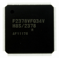
Manufacturer Part Number
DF2378RVFQ34V
Description
IC H8S MCU FLASH 512K 144LQFP
Manufacturer
Renesas Electronics America
Series
H8® H8S/2300r
Specifications of DF2378RVFQ34V
Core Processor
H8S/2000
Core Size
16-Bit
Speed
34MHz
Connectivity
I²C, IrDA, SCI, SmartCard
Peripherals
DMA, POR, PWM, WDT
Number Of I /o
97
Program Memory Size
512KB (512K x 8)
Program Memory Type
FLASH
Ram Size
32K x 8
Voltage - Supply (vcc/vdd)
3 V ~ 3.6 V
Data Converters
A/D 16x10b; D/A 6x8b
Oscillator Type
Internal
Operating Temperature
-20°C ~ 75°C
Package / Case
144-LQFP
For Use With
YLCDRSK2378 - KIT DEV EVAL H8S/2378 LCDYR0K42378FC000BA - KIT EVAL FOR H8S/2378HS0005KCU11H - EMULATOR E10A-USB H8S(X),SH2(A)EDK2378 - DEV EVAL KIT FOR H8S/2378
Lead Free Status / RoHS Status
Lead free / RoHS Compliant
Eeprom Size
-
Available stocks
Company
Part Number
Manufacturer
Quantity
Price
Company:

Part Number:
DF2378RVFQ34V
Manufacturer:
Renesas Electronics America
Quantity:
10 000


Section 1 Overview................................................................................................1
Table 1.1
Table 1.2
Section 2 CPU......................................................................................................35
Table 2.1
Table 2.2
Table 2.3
Table 2.4
Table 2.5
Table 2.6
Table 2.7
Table 2.8
Table 2.9
Table 2.10
Table 2.11
Table 2.12
Table 2.13
Section 3 MCU Operating Modes........................................................................71
Table 3.1
Table 3.2
Section 4 Exception Handling .............................................................................93
Table 4.1
Table 4.2
Table 4.3
Table 4.4
Section 5 Interrupt Controller ............................................................................103
Table 5.1
Table 5.2
Table 5.3
Table 5.4
Table 5.5
Section 6 Bus Controller (BSC).........................................................................137
Table 6.1
Pin Arrangement in Each Operating Mode ............................................................... 12
Pin Functions............................................................................................................. 18
Instruction Classification........................................................................................... 51
Operation Notation .................................................................................................... 52
Data Transfer Instructions ......................................................................................... 53
Arithmetic Operations Instructions ........................................................................... 54
Logic Operations Instructions ................................................................................... 56
Shift Instructions ....................................................................................................... 56
Bit Manipulation Instructions.................................................................................... 57
Branch Instructions ................................................................................................... 59
System Control Instructions ...................................................................................... 60
Block Data Transfer Instructions............................................................................... 61
Addressing Modes..................................................................................................... 63
Absolute Address Access Ranges ............................................................................. 64
Effective Address Calculation................................................................................... 66
MCU Operating Mode Selection............................................................................... 71
Pin Functions in Each Operating Mode..................................................................... 77
Exception Types and Priority .................................................................................... 93
Exception Handling Vector Table ............................................................................. 94
Status of CCR and EXR after Trace Exception Handling ......................................... 98
Status of CCR and EXR after Trap Instruction Exception Handling ........................ 99
Pin Configuration .................................................................................................... 105
Interrupt Sources, Vector Addresses, and Interrupt Priorities ................................. 122
Interrupt Control Modes.......................................................................................... 127
Interrupt Response Times........................................................................................ 132
Number of States in Interrupt Handling Routine Execution Statuses...................... 133
Pin Configuration .................................................................................................... 139
Tables
Rev.7.00 Mar. 18, 2009 page lix of lxvi
REJ09B0109-0700
Related parts for DF2378RVFQ34V
Image
Part Number
Description
Manufacturer
Datasheet
Request
R

Part Number:
Description:
KIT STARTER FOR M16C/29
Manufacturer:
Renesas Electronics America
Datasheet:

Part Number:
Description:
KIT STARTER FOR R8C/2D
Manufacturer:
Renesas Electronics America
Datasheet:

Part Number:
Description:
R0K33062P STARTER KIT
Manufacturer:
Renesas Electronics America
Datasheet:

Part Number:
Description:
KIT STARTER FOR R8C/23 E8A
Manufacturer:
Renesas Electronics America
Datasheet:

Part Number:
Description:
KIT STARTER FOR R8C/25
Manufacturer:
Renesas Electronics America
Datasheet:

Part Number:
Description:
KIT STARTER H8S2456 SHARPE DSPLY
Manufacturer:
Renesas Electronics America
Datasheet:

Part Number:
Description:
KIT STARTER FOR R8C38C
Manufacturer:
Renesas Electronics America
Datasheet:

Part Number:
Description:
KIT STARTER FOR R8C35C
Manufacturer:
Renesas Electronics America
Datasheet:

Part Number:
Description:
KIT STARTER FOR R8CL3AC+LCD APPS
Manufacturer:
Renesas Electronics America
Datasheet:
Part Number:
Description:
KIT STARTER FOR RX610
Manufacturer:
Renesas Electronics America
Datasheet:

Part Number:
Description:
KIT STARTER FOR R32C/118
Manufacturer:
Renesas Electronics America
Datasheet:

Part Number:
Description:
KIT DEV RSK-R8C/26-29
Manufacturer:
Renesas Electronics America
Datasheet:

Part Number:
Description:
KIT STARTER FOR SH7124
Manufacturer:
Renesas Electronics America
Datasheet:

Part Number:
Description:
KIT STARTER FOR H8SX/1622
Manufacturer:
Renesas Electronics America
Datasheet:

Part Number:
Description:
KIT DEV FOR SH7203
Manufacturer:
Renesas Electronics America
Datasheet: