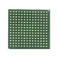
MCF5272VM66J Freescale Semiconductor, MCF5272VM66J Datasheet - Page 320

MCF5272VM66J
Manufacturer Part Number
MCF5272VM66J
Description
IC MCU 166MHZ 196MAPBGA
Manufacturer
Freescale Semiconductor
Series
MCF527xr
Datasheets
1.MCF5272CVF66J.pdf
(544 pages)
2.MCF5272CVF66J.pdf
(12 pages)
3.MCF5272VM66J.pdf
(44 pages)
Specifications of MCF5272VM66J
Core Processor
Coldfire V2
Core Size
32-Bit
Speed
66MHz
Connectivity
EBI/EMI, Ethernet, I²C, SPI, UART/USART, USB
Peripherals
DMA, WDT
Number Of I /o
32
Program Memory Size
16KB (4K x 32)
Program Memory Type
ROM
Ram Size
1K x 32
Voltage - Supply (vcc/vdd)
3 V ~ 3.6 V
Oscillator Type
External
Operating Temperature
0°C ~ 70°C
Package / Case
196-MAPBGA
Processor Series
MCF527x
Core
ColdFire V2
Data Bus Width
32 bit
Data Ram Size
64 KB
Interface Type
I2C, UART, Ethernet, SPI, USB, QSPI
Maximum Clock Frequency
166 MHz
Number Of Timers
4
Operating Supply Voltage
1.4 V to 1.6 V
Maximum Operating Temperature
+ 85 C
Mounting Style
SMD/SMT
3rd Party Development Tools
JLINK-CF-BDM26, EWCF
Development Tools By Supplier
NNDK-MOD5272-KIT, NNDK-MOD5270-KIT
Minimum Operating Temperature
- 40 C
Lead Free Status / RoHS Status
Lead free / RoHS Compliant
Eeprom Size
-
Data Converters
-
Lead Free Status / Rohs Status
Lead free / RoHS Compliant
Available stocks
Company
Part Number
Manufacturer
Quantity
Price
Company:
Part Number:
MCF5272VM66J
Manufacturer:
FREESCAL
Quantity:
416
Company:
Part Number:
MCF5272VM66J
Manufacturer:
Freescale
Quantity:
178
Company:
Part Number:
MCF5272VM66J
Manufacturer:
Freescale Semiconductor
Quantity:
10 000
- Current page: 320 of 544
- Download datasheet (7Mb)
Physical Layer Interface Controller (PLIC)
13.5.12 GCI Monitor Channel Receive Registers (P0GMR–P3GMR)
All bits in these registers are read only and are initialized to 0x00FF on hardware or software reset.
PnGMR are 16-bit registers containing the received monitor channel bits for each of the four receive ports
on the MCF5272.
A byte of monitor channel data received on a certain port is put into an associated register using the format
shown in
registers.
13-24
15–11
Bits
7–0
10
Reset
9
8
Field
Addr
R/W
Figure
15
Name
EOM
MC
AB
—
M
13-24. A maskable interrupt is generated when a byte is written into any of these four
Figure 13-24. GCI Monitor Channel Receive Registers (P0GMR–P3GMR)
Reserved, should be cleared.
End of message.
0 Default at reset.
1 Indicates to the CPU that an end-of-message condition has been recognized on the E bit. EOM is
Abort.
0 Default at reset.
1 Indicates that the GCI controller has recognized an abort condition and is acknowledging the abort.
Monitor change.
0 Default at reset.
1 Indicates to the CPU that the monitor channel data byte written to the respective PnGMR register
Monitor channel data byte.
MCF5272 ColdFire
—
MBAR + 0x360 (P0GMR); 0x362 (P1GMR); 0x364 (P2GMR); 0x366 (P3GMR)
automatically cleared when the PnGMR register has been read by the CPU.
It is automatically cleared by the CPU when the PnGMR register has been read.
has changed and that the data is available for processing. Automatically cleared by the CPU when
the PnGMR register has been read. Clearing this bit by reading this register also clears the
aperiodic GMR interrupt.
Table 13-7. P0GMR–P3GMR Field Descriptions
11
®
EOM
Integrated Microprocessor User’s Manual, Rev. 3
10
AB
0000_0000_1111_1111
9
Read Only
MC
8
Description
7
M
Freescale Semiconductor
0
Related parts for MCF5272VM66J
Image
Part Number
Description
Manufacturer
Datasheet
Request
R
Part Number:
Description:
Mcf5272 Coldfire Integrated Microprocessor User
Manufacturer:
Freescale Semiconductor, Inc
Datasheet:

Part Number:
Description:
MCF5272 Interrupt Service Routine for the Physical Layer Interface Controller
Manufacturer:
Freescale Semiconductor / Motorola
Datasheet:
Part Number:
Description:
Manufacturer:
Freescale Semiconductor, Inc
Datasheet:
Part Number:
Description:
Manufacturer:
Freescale Semiconductor, Inc
Datasheet:
Part Number:
Description:
Manufacturer:
Freescale Semiconductor, Inc
Datasheet:
Part Number:
Description:
Manufacturer:
Freescale Semiconductor, Inc
Datasheet:
Part Number:
Description:
Manufacturer:
Freescale Semiconductor, Inc
Datasheet:
Part Number:
Description:
Manufacturer:
Freescale Semiconductor, Inc
Datasheet:
Part Number:
Description:
Manufacturer:
Freescale Semiconductor, Inc
Datasheet:
Part Number:
Description:
Manufacturer:
Freescale Semiconductor, Inc
Datasheet:
Part Number:
Description:
Manufacturer:
Freescale Semiconductor, Inc
Datasheet:
Part Number:
Description:
Manufacturer:
Freescale Semiconductor, Inc
Datasheet:
Part Number:
Description:
Manufacturer:
Freescale Semiconductor, Inc
Datasheet:
Part Number:
Description:
Manufacturer:
Freescale Semiconductor, Inc
Datasheet:
Part Number:
Description:
Manufacturer:
Freescale Semiconductor, Inc
Datasheet:


