ADSP-21364BSWZ-1AA Analog Devices Inc, ADSP-21364BSWZ-1AA Datasheet - Page 11
ADSP-21364BSWZ-1AA
Manufacturer Part Number
ADSP-21364BSWZ-1AA
Description
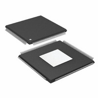
IC DSP 32BIT 333MHZ EPAD 144LQFP
Manufacturer
Analog Devices Inc
Series
SHARC®r
Type
Fixed/Floating Pointr
Datasheet
1.ADSP-21363KSWZ-1AA.pdf
(56 pages)
Specifications of ADSP-21364BSWZ-1AA
Interface
DAI, SPI
Clock Rate
333MHz
Non-volatile Memory
ROM (512 kB)
On-chip Ram
384kB
Voltage - I/o
3.30V
Voltage - Core
1.20V
Operating Temperature
-40°C ~ 85°C
Mounting Type
Surface Mount
Package / Case
144-LQFP Exposed Pad, 144-eLQFP, 144-HLQFP
Frequency
333MHz
Supply Voltage
1.2V
Embedded Interface Type
Serial, SPI
Supply Voltage Range
1.14V To 1.26V
Operating Temperature Range
-40°C To +85°C
Digital Ic Case
RoHS Compliant
No. Of Bits
32 / 40
Rohs Compliant
Yes
Package
144LQFP EP
Numeric And Arithmetic Format
Floating-Point
Maximum Speed
333 MHz
Ram Size
384 KB
Device Million Instructions Per Second
333 MIPS
Lead Free Status / RoHS Status
Lead free / RoHS Compliant
Available stocks
Company
Part Number
Manufacturer
Quantity
Price
Company:

Part Number:
ADSP-21364BSWZ-1AA
Manufacturer:
Analog Devices Inc
Quantity:
10 000


PIN FUNCTION DESCRIPTIONS
The processor’s pin definitions are listed below. Inputs identi-
fied as synchronous (S) must meet timing requirements with
respect to CLKIN (or with respect to TCK for TMS and TDI).
Table 6. Pin Descriptions
Pin
AD15–0
RD
WR
ALE
FLAG[0]/IRQ0/SPI
FLG[0]
FLAG[1]/IRQ1/SPI
FLG[1]
FLAG[2]/IRQ2/SPI
FLG[2]
FLAG[3]/TMREXP/
SPIFLG[3]
DAI_P20–1
The following symbols appear in the Type column of
S = synchronous, (A/D) = active drive, (O/D) = open drain, and T = three-state, (pd) = pull-down resistor, (pu) = pull-up resistor.
Type
I/O/T
(pu)
O
(pu)
O
(pu)
O
(pd)
I/O
I/O
I/O
I/O
I/O/T
(pu)
ADSP-21362/ADSP-21363/ADSP-21364/ADSP-21365/ADSP-21366
State During and
After Reset
Three-state with
pull-up enabled
Three-state, driven
high
Three-state, driven
high
Three-state, driven
low
FLAG[0] INPUT
FLAG[1] INPUT
FLAG[2] INPUT
FLAG[3] INPUT
Three-state with
programmable
pull-up
1
1
1
Rev. G | Page 11 of 56 | March 2011
Table
Function
Parallel Port Address/Data. The ADSP-2136x parallel port and its corresponding DMA
unit output addresses and data for peripherals on these multiplexed pins. The multiplex
state is determined by the ALE pin. The parallel port can operate in either 8-bit or 16-bit
mode. Each AD pin has a 22.5 kΩ internal pull-up resistor. For details about the AD pin
operation, refer to the ADSP-2136x SHARC Processor Hardware Reference .
For 8-bit mode: ALE is automatically asserted whenever a change occurs in the upper 16
external address bits, ADDR23–8; ALE is used in conjunction with an external latch to
retain the values of the ADDR23–8.
For detailed information on I/O operations and pin multiplexing, refer to the ADSP-2136x
SHARC Processor Hardware Reference.
Parallel Port Read Enable. RD is asserted low whenever the processor reads 8-bit or 16-
bit data from an external memory device. When AD15–0 are flags, this pin remains
deasserted. RD has a 22.5 kΩ internal pull-up resistor.
Parallel Port Write Enable. WR is asserted low whenever the processor writes 8-bit or
16-bit data to an external memory device. When AD15–0 are flags, this pin remains
deasserted. WR has a 22.5 kΩ internal pull-up resistor.
Parallel Port Address Latch Enable. ALE is asserted whenever the processor drives a
new address on the parallel port address pins. On reset, ALE is active high. However, it
can be reconfigured using software to be active low. When AD15–0 are flags, this pin
remains deasserted. ALE has a 20 kΩ internal pull-down resistor.
FLAG0/Interrupt Request0/SPI0 Slave Select.
FLAG1/Interrupt Request1/SPI1 Slave Select.
FLAG2/Interrupt Request 2/SPI2 Slave Select.
FLAG3/Timer Expired/SPI3 Slave Select.
Digital Audio Interface Pins. These pins provide the physical interface to the SRU. The
SRU configuration registers define the combination of on-chip peripheral inputs or
outputs connected to the pin and to the pin’s output enable. The configuration registers
of these peripherals then determine the exact behavior of the pin. Any input or output
signal present in the SRU can be routed to any of these pins. The SRU provides the
connection from the serial ports, input data port, precision clock generators and timers,
sample rate converters and SPI to the DAI_P20–1 pins. These pins have internal 22.5 kΩ
pull-up resistors that are enabled on reset. These pull-ups can be disabled using the
DAI_PIN_PULLUP register.
6: A = asynchronous, G = ground, I = input, O = output, P = power supply,
Inputs identified as asynchronous (A) can be asserted asynchro-
nously to CLKIN (or to TCK for TRST). Tie or pull unused
inputs to V
DAI_Px, SPICLK, MISO, MOSI, EMU, TMS, TRST, TDI, and
AD15–0. Note: These pins have pull-up resistors.
DDEXT
or GND, except for the following:
Related parts for ADSP-21364BSWZ-1AA
Image
Part Number
Description
Manufacturer
Datasheet
Request
R

Part Number:
Description:
±1.7g Dual-Axis IMEMS Accelerometer Evaluation Board
Manufacturer:
Analog Devices Inc
Datasheet:

Part Number:
Description:
Inertial Sensor Evaluation System
Manufacturer:
Analog Devices Inc
Datasheet:
Part Number:
Description:
Manufacturer:
Analog Devices Inc
Datasheet:
Part Number:
Description:
Manufacturer:
Analog Devices Inc
Datasheet:
Part Number:
Description:
Manufacturer:
Analog Devices Inc
Datasheet:
Part Number:
Description:
Manufacturer:
Analog Devices Inc
Datasheet:
Part Number:
Description:
Manufacturer:
Analog Devices Inc
Datasheet:
Part Number:
Description:
Manufacturer:
Analog Devices Inc
Datasheet:
Part Number:
Description:
Manufacturer:
Analog Devices Inc
Datasheet:
Part Number:
Description:
Manufacturer:
Analog Devices Inc
Datasheet:
Part Number:
Description:
Manufacturer:
Analog Devices Inc
Datasheet:
Part Number:
Description:
Manufacturer:
Analog Devices Inc
Datasheet:
Part Number:
Description:
Manufacturer:
Analog Devices Inc
Datasheet: