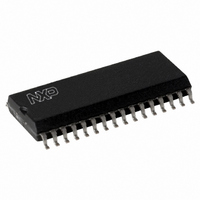
MFRC50001T/0FE,112 NXP Semiconductors, MFRC50001T/0FE,112 Datasheet - Page 83

MFRC50001T/0FE,112
Manufacturer Part Number
MFRC50001T/0FE,112
Description
IC MIFARE READER 32-SOIC
Manufacturer
NXP Semiconductors
Series
MIFARE®r
Specifications of MFRC50001T/0FE,112
Rf Type
Read Only
Frequency
13.56MHz
Features
ISO14443-A, ISO14443-B, ISO15693
Package / Case
32-SOIC (0.300", 7.50mm Width)
Product
RFID Readers
Operating Temperature Range
- 25 C to + 85 C
Lead Free Status / RoHS Status
Lead free / RoHS Compliant
Lead Free Status / RoHS Status
Lead free / RoHS Compliant, Lead free / RoHS Compliant
Other names
568-2222-5
935268039112
MFRC500
MFRC51T0FED
935268039112
MFRC500
MFRC51T0FED
Available stocks
Company
Part Number
Manufacturer
Quantity
Price
Part Number:
MFRC50001T/0FE,112
Manufacturer:
NXP/恩智浦
Quantity:
20 000
NXP Semiconductors
12. Limiting values
Table 146. Limiting values
In accordance with the Absolute Maximum Rating System (IEC 60134).
13. Characteristics
Table 147. Operating condition range
MFRC500_33
Product data sheet
PUBLIC
Symbol
T
T
V
V
V
|V
Symbol
T
V
V
V
V
amb
stg
amb
DDD
DDA
DD(TVDD)
DDD
DDA
DD(TVDD)
ESD
i
|
11.6.4.1 Authent2 command effects
Parameter
ambient temperature
storage temperature
digital supply voltage
analog supply voltage
TVDD supply voltage
input voltage (absolute value)
13.1 Operating condition range
Parameter
ambient temperature
digital supply voltage
analog supply voltage
TVDD supply voltage
electrostatic discharge voltage Human Body Model (HBM); 1.5 kΩ,
If the Authent2 command is successful, the authenticity of card and the MFRC500 are
proved. This automatically sets the Crypto1On control bit. When bit Crypto1On = logic 1,
all further card communication is encrypted using the Crypto1 security algorithm. If the
Authent2 command fails, bit Crypto1On is cleared (Crypto1On = logic 0).
Remark: The Crypto1On flag can only be set by a successfully executed Authent2
command and not by the microprocessor. The microprocessor can clear bit Crypto1On to
continue with unencrypted (plain) card communication.
Remark: The Authent2 command must be executed immediately after a successful
Authent1 command; see
stored in the key buffer and those on the card must match.
All information provided in this document is subject to legal disclaimers.
Conditions
on any digital pin to DVSS
on pin RX to AVSS
Conditions
-
DVSS = AVSS = TVSS = 0 V
100 pF
Machine Model (MM); 0.75 μH,
200 pF
DVSS = AVSS = TVSS = 0 V
DVSS = AVSS = TVSS = 0 V
Rev. 3.3 — 15 March 2010
Section 11.6.3 “Authent1 command
048033
Highly Integrated ISO/IEC 14443 A Reader IC
Min
−40
−40
−0.5
−0.5
−0.5
−0.5
−0.5
Min
−25
4.5
4.5
3.0
-
-
0Ch”. In addition, the keys
Max
+150
+150
+6
+6
+6
V
V
DDD
DDA
Typ
+25
5.0
5.0
5.0
-
-
+ 0.5
+ 0.5
MFRC500
© NXP B.V. 2010. All rights reserved.
Max
+85
5.5
5.5
5.5
1000
100
Unit
°C
°C
V
V
V
V
V
83 of 110
Unit
°C
V
V
V
V
V


