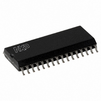
MFRC50001T/0FE,112 NXP Semiconductors, MFRC50001T/0FE,112 Datasheet - Page 79

MFRC50001T/0FE,112
Manufacturer Part Number
MFRC50001T/0FE,112
Description
IC MIFARE READER 32-SOIC
Manufacturer
NXP Semiconductors
Series
MIFARE®r
Specifications of MFRC50001T/0FE,112
Rf Type
Read Only
Frequency
13.56MHz
Features
ISO14443-A, ISO14443-B, ISO15693
Package / Case
32-SOIC (0.300", 7.50mm Width)
Product
RFID Readers
Operating Temperature Range
- 25 C to + 85 C
Lead Free Status / RoHS Status
Lead free / RoHS Compliant
Lead Free Status / RoHS Status
Lead free / RoHS Compliant, Lead free / RoHS Compliant
Other names
568-2222-5
935268039112
MFRC500
MFRC51T0FED
935268039112
MFRC500
MFRC51T0FED
Available stocks
Company
Part Number
Manufacturer
Quantity
Price
Part Number:
MFRC50001T/0FE,112
Manufacturer:
NXP/恩智浦
Quantity:
20 000
NXP Semiconductors
MFRC500_33
Product data sheet
PUBLIC
11.3.2.1 ReadE2 command error flags
11.4.1.1 Register assignment
11.3.2 ReadE2 command 03h
11.4.1 LoadConfig command 07h
11.4 Diverse commands
Table 137. ReadE2 command 03h
The ReadE2 command interprets the first two bytes stored in the FIFO buffer as the
EEPROM starting byte address. The next byte specifies the number of data bytes
returned.
When all three argument bytes are available in the FIFO buffer, the specified number of
data bytes is copied from the EEPROM into the FIFO buffer, starting from the given
EEPROM starting byte address.
The ReadE2 command can only be triggered by the microprocessor and it automatically
stops when all data has been copied.
Reading is restricted to EEPROM blocks 8h to 1Fh (key memory area). Reading from
these addresses sets the flag AccessErr = logic 1.
Addresses above 1FFh are taken as modulo 200h; see
EEPROM memory organization.
Table 138. LoadConfig command 07h
The LoadConfig command interprets the first two bytes found in the FIFO buffer as the
EEPROM starting byte address. When the two argument bytes are available in the FIFO
buffer, 32 bytes from the EEPROM are copied into the Control and other relevant
registers, starting at the EEPROM starting byte address. The LoadConfig command can
only be started by the microprocessor and it automatically stops when all relevant
registers have been copied.
The 32 bytes of EEPROM content are written to the MFRC500 registers 10h to register
2Fh; see
Remark: The procedure for the register assignment is the same as it is for the StartUp
initialization (see
address for the startup initialization is fixed to 10h (block 1, byte 0). However, it can be
chosen with the LoadConfig command.
Command
ReadE2
Command
LoadConfig
Section 9.2 on page 10
Value Action
03h
Value Action
07h
All information provided in this document is subject to legal disclaimers.
Section 9.7.3 on page
reads EEPROM data and
stores it in the FIFO buffer
reads data from EEPROM and
initializes the registers
Rev. 3.3 — 15 March 2010
048033
for the EEPROM memory organization.
25). The difference is, the EEPROM starting byte
Highly Integrated ISO/IEC 14443 A Reader IC
Arguments
start address LSB
start address MSB
number of data bytes
Arguments and
data
start address LSB
start address MSB
Section 9.2 on page 10
MFRC500
© NXP B.V. 2010. All rights reserved.
Returned data
data bytes
Returned data
-
-
for the
79 of 110


