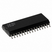
MFRC50001T/0FE,112 NXP Semiconductors, MFRC50001T/0FE,112 Datasheet - Page 24

MFRC50001T/0FE,112
Manufacturer Part Number
MFRC50001T/0FE,112
Description
IC MIFARE READER 32-SOIC
Manufacturer
NXP Semiconductors
Series
MIFARE®r
Specifications of MFRC50001T/0FE,112
Rf Type
Read Only
Frequency
13.56MHz
Features
ISO14443-A, ISO14443-B, ISO15693
Package / Case
32-SOIC (0.300", 7.50mm Width)
Product
RFID Readers
Operating Temperature Range
- 25 C to + 85 C
Lead Free Status / RoHS Status
Lead free / RoHS Compliant
Lead Free Status / RoHS Status
Lead free / RoHS Compliant, Lead free / RoHS Compliant
Other names
568-2222-5
935268039112
MFRC500
MFRC51T0FED
935268039112
MFRC500
MFRC51T0FED
Available stocks
Company
Part Number
Manufacturer
Quantity
Price
Part Number:
MFRC50001T/0FE,112
Manufacturer:
NXP/恩智浦
Quantity:
20 000
NXP Semiconductors
MFRC500_33
Product data sheet
PUBLIC
9.6.2 Soft power-down mode
9.6.3 Standby mode
9.6.4 Automatic receiver power-down
Table 19.
Soft power-down mode is entered immediately using the Control register bit PowerDown.
All internal current sinks, including the oscillator buffer, are switched off. The digital input
buffers are not separated from the input pads and keep their functionality. In addition, the
digital output pins do not change their state.
After resetting the Control register bit PowerDown, the bit indicating Soft power-down
mode is only cleared after 512 clock cycles. Resetting it does not immediately clear it. The
PowerDown bit is automatically cleared when the Soft power-down mode is exited.
Remark: When the internal oscillator is used, time (t
become stable. This is because the internal oscillator is supplied by V
cycles will not be detected by the internal logic until V
The Standby mode is immediately entered when the Control register StandBy bit is set. All
internal current sinks, including the internal digital clock buffer are switched off. However,
the oscillator buffer is not switched off.
The digital input buffers are not separated by the input pads, keeping their functionality
and the digital output pins do not change their state. In addition, the oscillator does not
need time to wake-up.
After resetting the Control register StandBy bit, it takes four clock cycles on pin OSCIN for
Standby mode to exit. Resetting bit StandBy does not immediately clear it. It is
automatically cleared when the Standby mode is exited.
It is a power saving feature to switch off the receiver circuit when it is not needed. Setting
bit RxAutoPD = logic 1, automatically powers down the receiver when it is not in use.
Setting bit RxAutoPD = logic 0, keeps the receiver continuously powered up.
Symbol
RX
VMID
RSTPD
OSCOUT
Signal on pins during Hard power-down
All information provided in this document is subject to legal disclaimers.
Pin
29
30
31
32
Rev. 3.3 — 15 March 2010
048033
Type
I
A
I
O
Highly Integrated ISO/IEC 14443 A Reader IC
Description
not changed
pulled to V
not changed
HIGH
…continued
osc
DDA
DDA
) is required for the oscillator to
is stable.
MFRC500
DDA
© NXP B.V. 2010. All rights reserved.
and any clock
24 of 110


