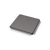
71M6534-IGT/F Maxim Integrated Products, 71M6534-IGT/F Datasheet - Page 77

71M6534-IGT/F
Manufacturer Part Number
71M6534-IGT/F
Description
IC ENERY METER 3PH 128K 120-LQFP
Manufacturer
Maxim Integrated Products
Datasheet
1.71M6533H-IGTF.pdf
(132 pages)
Specifications of 71M6534-IGT/F
Mounting Style
SMD/SMT
Package / Case
LQFP-120
Lead Free Status / RoHS Status
Lead free / RoHS Compliant
Available stocks
Company
Part Number
Manufacturer
Quantity
Price
Company:
Part Number:
71M6534-IGT/F
Manufacturer:
HONEYWELL
Quantity:
10
Company:
Part Number:
71M6534-IGT/F
Manufacturer:
Maxim Integrated
Quantity:
10 000
Part Number:
71M6534-IGT/F
Manufacturer:
MAXIM/美信
Quantity:
20 000
4.11 Flash Programming
Operational or test code can be programmed into the flash memory using either an in-circuit emulator or
the Flash Programmer Module (TFP-2). The flash programming procedure uses the E_RST, E_RXTX,
and E_TCLK pins. The FL_BANK[2:0] field must be set to the value corresponding to the bank that is
being programmed.
4.12 MPU Firmware Library
All application-specific MPU functions mentioned in
Teridian demonstration source code. The code is available as part of the Demonstration Kit for the
71M6533/71M6534. The Demonstration Kits come with the 71M6533/71M6534 preprogrammed with demo
firmware and mounted on a functional sample meter Demo Board. The Demo Boards allow for quick and
efficient evaluation of the IC without having to write firmware or having to supply an in-circuit emulator
(ICE).
4.13 Crystal Oscillator
The oscillator drives a standard 32.768 kHz watch crystal. The oscillator has been designed specifically
to handle these crystals and is compatible with their high impedance and limited power handling capability.
The oscillator power dissipation is very low to maximize the lifetime of any battery backup device attached
to VBAT.
Board layouts with minimum capacitance from XIN to XOUT will require less battery current. Good
layouts will have XIN and XOUT shielded from each other.
Rev 2
Meters equipped with batteries need to contain code that transitions the chip to SLEEP mode as
soon as the battery is attached in production. Otherwise, remaining in BROWNOUT mode would
add unnecessary drain to the battery.
For best rejection of electromagnetic interference, connect the crystal body and the ground
terminals of the two crystal capacitors to GNDD through a ferrite bead. No external resistor
should be connected across the crystal, since the oscillator is self-biasing.
Battery or
Super - Cap
Power
Supply
+
-
Figure 44: Connecting a Battery
Section 3 Application Information
V3P3A
DIO
V3P3SYS
VBAT
71M6533/6534
are featured in the
77


