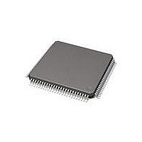
71M6534-IGT/F Maxim Integrated Products, 71M6534-IGT/F Datasheet - Page 51

71M6534-IGT/F
Manufacturer Part Number
71M6534-IGT/F
Description
IC ENERY METER 3PH 128K 120-LQFP
Manufacturer
Maxim Integrated Products
Datasheet
1.71M6533H-IGTF.pdf
(132 pages)
Specifications of 71M6534-IGT/F
Mounting Style
SMD/SMT
Package / Case
LQFP-120
Lead Free Status / RoHS Status
Lead free / RoHS Compliant
Available stocks
Company
Part Number
Manufacturer
Quantity
Price
Company:
Part Number:
71M6534-IGT/F
Manufacturer:
HONEYWELL
Quantity:
10
Company:
Part Number:
71M6534-IGT/F
Manufacturer:
Maxim Integrated
Quantity:
10 000
Part Number:
71M6534-IGT/F
Manufacturer:
MAXIM/美信
Quantity:
20 000
A read transaction performed at 2 Mbit/s is shown in
Figure 16
The SPI_FLAG flag bit will be set upon every SPI transaction regardless of whether the command is 11xx
xxxx or 10xx xxxx. The SP_ADDR[15:0] bit field is for writing purposes by the host only. Data read from
SP_ADDR[15:0] will not contain the next available SPI address after an auto-increment operation.
The last issued SPI command and address (if part of the command) are available to the MPU in registers
SP_CMD and SP_ADDR.
The SPI port supports data transfers at 1 Mb/s in mission mode, and 16 kb/s in BROWNOUT mode. The
SPI port may operate at higher speeds
following conditions apply:
Certain I/O RAM registers can be written and read using the SPI port (see
takes priority over the I/O RAM bus, and SPI operation may fail without notice. To avoid this situation, the
SPI host should send a command other than 11xxxxxx or 10xxxxxx (read or write) before the actual read
or write command. The SPI slave interface will load the command register and generate an INT2 interrupt
upon receiving the command. The MPU should service the interrupt and halt any external data memory
operations to effectively grant the bus to the SPI. When the SPI host finishes, it should send another
Rev 2
Command
11xx xxxx ADDR Byte0 ... ByteN
10xx xxxx ADDR Byte0 ... ByteN
0xxx xxxx ADDR Byte0 ... ByteN
•
•
PSDO
Write operations can be issued by the host at up to 2 Mbits/s.
Read operations can be issued at up to 2 Mbit/s, if a minimum gap of 1 µs is inserted by the host
between the last PSCK clock of the SPI address and the first clock of the data read. This gap will
give the hardware of the 71M653x sufficient time to fetch and provide the read data.
PSDI
PCSZ
PCLK
illustrates the SPI Interface read and write timing.
7 6 5 4 3
Command
Figure 15: SPI Slave Port: Read Operation with Gap
0.5 µs
2
Table 47: SPI Command Description
1 0 15
Description
Read data starting at ADDR. The address value provided in ADDR will
be automatically incremented until PCSZ is raised. Upon completion:
SP__CMD=11xx xxxx
An MPU interrupt is generated.
Write data starting at ADDR. The address value provided in ADDR will
be automatically incremented until PCSZ is raised.
SP_CMD=10xx xxxx
An MPU interrupt is generated.
Commands other than 1xxx xxxx are ignored, but an SPI interrupt is still
generated when PCSZ goes high.
under certain
14 ……………...….
Address
Figure
conditions. For SPI speeds higher than 1 Mbit/s, the
6 5 4 3 1 0
15.
7 6 5 4 3
Table
1 µs min.
Data
48). However, the MPU
2
1 0
Upon completion:
51


