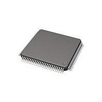
71M6534-IGT/F Maxim Integrated Products, 71M6534-IGT/F Datasheet - Page 17

71M6534-IGT/F
Manufacturer Part Number
71M6534-IGT/F
Description
IC ENERY METER 3PH 128K 120-LQFP
Manufacturer
Maxim Integrated Products
Datasheet
1.71M6533H-IGTF.pdf
(132 pages)
Specifications of 71M6534-IGT/F
Mounting Style
SMD/SMT
Package / Case
LQFP-120
Lead Free Status / RoHS Status
Lead free / RoHS Compliant
Available stocks
Company
Part Number
Manufacturer
Quantity
Price
Company:
Part Number:
71M6534-IGT/F
Manufacturer:
HONEYWELL
Quantity:
10
Company:
Part Number:
71M6534-IGT/F
Manufacturer:
Maxim Integrated
Quantity:
10 000
Part Number:
71M6534-IGT/F
Manufacturer:
MAXIM/美信
Quantity:
20 000
requires two Data RAM accesses. The second access is guaranteed to be available because the MPU
cannot access the XRAM on two consecutive instructions unless it is using the same address.
In addition to the reduction of wait states, this arrangement permits the MPU to easily use unneeded CE
data memory. Likewise, the amount of memory the CE uses is not limited by the size of a dedicated CE
data RAM.
The Data RAM is 32 bits wide and uses an external multiplexer so as to appear byte-wide to the MPU.
The Data RAM hardware will convert an MPU byte write operation into a read-modify-write operation that
1.3.5 CE Functional Overview
The ADC processes one sample per channel per multiplexer cycle.
samples taken during one multiplexer cycle (phases A, B, and C being processed). During an ALT
multiplexer sequence, missing samples are filled in by the CE.
The number of samples processed during one accumulation cycle is controlled by PRE_SAMPS[1:0] (I/O
RAM 0x2001[7:6]) and SUM_CYCLES[5:0] (I/O RAM 0x2001[5:0]). The integration time for each energy
output is:
For example, PRE_SAMPS[1:0] = 42 and SUM_CYCLES[5:0] = 50 will establish 2100 samples per accumulation
cycle. PRE_SAMPS[1:0] = 100 and SUM_CYCLES[5:0] = 21 will result in the exact same accumulation
cycle of 2100 samples or 833 ms. After an accumulation cycle is completed, the XFER_BUSY interrupt
signals to the MPU that accumulated data are available.
The end of each multiplexer cycle is signaled to the MPU by the CE_BUSY interrupt. At the end of each
multiplexer cycle, status information, such as sag data and the digitized input signal, is available to the MPU.
Rev 2
PRE_SAMPS[1:0] * SUM_CYCLES[5:0] / 2520.6, where 2520.6 is the sample rate in Hz
B
B
IA
IA
1/2520.6Hz = 397µs
1/2520.6Hz = 397µs
Figure 5: Samples from Multiplexer Cycle
VA
VA
VB
VB
IB
IB
IC
IC
VC
VC
13/32768Hz = 397µs
13/32768Hz = 397µs
per mux cycle
per mux cycle
2/32768Hz =
2/32768Hz =
61.04µs
61.04µs
A
A
Figure 5
C
C
shows the timing of the
17


