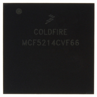
MCF5214CVF66 Freescale Semiconductor, MCF5214CVF66 Datasheet - Page 462

MCF5214CVF66
Manufacturer Part Number
MCF5214CVF66
Description
IC MPU 32BIT COLDF 256-MAPBGA
Manufacturer
Freescale Semiconductor
Series
MCF521xr
Datasheet
1.MCF5216CVM66J.pdf
(766 pages)
Specifications of MCF5214CVF66
Core Processor
Coldfire V2
Core Size
32-Bit
Speed
66MHz
Connectivity
CAN, EBI/EMI, I²C, SPI, UART/USART
Peripherals
DMA, LVD, POR, PWM, WDT
Number Of I /o
142
Program Memory Size
256KB (256K x 8)
Program Memory Type
FLASH
Ram Size
64K x 8
Voltage - Supply (vcc/vdd)
2.7 V ~ 3.6 V
Data Converters
A/D 8x12b
Oscillator Type
Internal
Operating Temperature
-40°C ~ 85°C
Package / Case
256-MAPBGA
Package
256MA-BGA
Device Core
ColdFire
Family Name
MCF521x
Maximum Speed
66 MHz
Operating Supply Voltage
3.3 V
Data Bus Width
32 Bit
Number Of Programmable I/os
142
Interface Type
QSPI/UART/I2C/CAN
On-chip Adc
8-chx10-bit
Number Of Timers
8
Lead Free Status / RoHS Status
Contains lead / RoHS non-compliant
Eeprom Size
-
Available stocks
Company
Part Number
Manufacturer
Quantity
Price
Company:
Part Number:
MCF5214CVF66
Manufacturer:
Freescale Semiconductor
Quantity:
10 000
Company:
Part Number:
MCF5214CVF66J
Manufacturer:
Freescale Semiconductor
Quantity:
10 000
- Current page: 462 of 766
- Download datasheet (9Mb)
I
24.3.2
The master sends the slave address in the first byte after the START signal (B). After the seven-bit calling
address, it sends the R/W bit (C), which tells the slave data transfer direction (0 equals write transfer, 1
equals read transfer).
Each slave must have a unique address. An I
be master and slave at the same time.
The slave whose address matches that sent by the master pulls I2C_SDA low at the ninth serial clock (D)
to return an acknowledge bit.
24.3.3
When successful slave addressing is achieved, data transfer can proceed (see E in
byte-by-byte basis in the direction specified by the R/W bit sent by the calling master.
Data can be changed only while I2C_SCL is low and must be held stable while I2C_SCL is high, as
Figure 24-7
device must acknowledge each byte by pulling I2C_SDA low at the ninth clock; therefore, a data byte
transfer takes nine clock pulses. See
24-8
2
C Interface
I2C_SCL
I2C_SDA
I2C_SCL
I2C_SDA
START
Signal
A
Slave Address Transmission
Data Transfer
shows. I2C_SCL is pulsed once for each data bit, with the msb being sent first. The receiving
START
Signal
Bit7
1
AD7 AD6 AD5 AD4 AD3 AD2 AD1 R/W
msb
1
Bit6
2
2
MCF5282 and MCF5216 ColdFire Microcontroller User’s Manual, Rev. 3
Bit5
Slave Address
3
Calling Address
3
Figure 24-7. I
Bit4
B
4
4
Bit3
5
5
Figure
Bit2
6
6
Figure 24-8. Data Transfer
2
C Standard Communication Protocol
Bit1
7
7
24-8.
2
(Byte complete)
Interrupt bit set
R/W
lsb
C master must not transmit its own slave address; it cannot
8
C
R/W
Bit0
I2C_
Interrupt is serviced
8
ACK from
Receiver
ACK
Bit
9
SCL held low while
9
D
XXX
I2C_
Interrupt is serviced
Bit7
1
(Byte Complete)
Interrupt Bit Set
SCL held low while
msb
D7
Bit6
1
2
E
D6
2
Bit5
3
Data Byte
D5
3
Bit4
4
Data Byte
D4
4
Bit3
5
D3
5
Bit2
6
D2
6
Figure
Freescale Semiconductor
Bit1
7
D1
7
Bit0
lsb
D0
24-7) on a
8
8
ACK Bit
ACK
No
No
Bit
9
9
STOP
Signal
STOP
Signal
F
Related parts for MCF5214CVF66
Image
Part Number
Description
Manufacturer
Datasheet
Request
R
Part Number:
Description:
Manufacturer:
Freescale Semiconductor, Inc
Datasheet:
Part Number:
Description:
Manufacturer:
Freescale Semiconductor, Inc
Datasheet:
Part Number:
Description:
Manufacturer:
Freescale Semiconductor, Inc
Datasheet:
Part Number:
Description:
Manufacturer:
Freescale Semiconductor, Inc
Datasheet:
Part Number:
Description:
Manufacturer:
Freescale Semiconductor, Inc
Datasheet:
Part Number:
Description:
Manufacturer:
Freescale Semiconductor, Inc
Datasheet:
Part Number:
Description:
Manufacturer:
Freescale Semiconductor, Inc
Datasheet:
Part Number:
Description:
Manufacturer:
Freescale Semiconductor, Inc
Datasheet:
Part Number:
Description:
Manufacturer:
Freescale Semiconductor, Inc
Datasheet:
Part Number:
Description:
Manufacturer:
Freescale Semiconductor, Inc
Datasheet:
Part Number:
Description:
Manufacturer:
Freescale Semiconductor, Inc
Datasheet:
Part Number:
Description:
Manufacturer:
Freescale Semiconductor, Inc
Datasheet:
Part Number:
Description:
Manufacturer:
Freescale Semiconductor, Inc
Datasheet:
Part Number:
Description:
Manufacturer:
Freescale Semiconductor, Inc
Datasheet:
Part Number:
Description:
Manufacturer:
Freescale Semiconductor, Inc
Datasheet:


