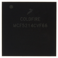
MCF5214CVF66 Freescale Semiconductor, MCF5214CVF66 Datasheet - Page 422

MCF5214CVF66
Manufacturer Part Number
MCF5214CVF66
Description
IC MPU 32BIT COLDF 256-MAPBGA
Manufacturer
Freescale Semiconductor
Series
MCF521xr
Datasheet
1.MCF5216CVM66J.pdf
(766 pages)
Specifications of MCF5214CVF66
Core Processor
Coldfire V2
Core Size
32-Bit
Speed
66MHz
Connectivity
CAN, EBI/EMI, I²C, SPI, UART/USART
Peripherals
DMA, LVD, POR, PWM, WDT
Number Of I /o
142
Program Memory Size
256KB (256K x 8)
Program Memory Type
FLASH
Ram Size
64K x 8
Voltage - Supply (vcc/vdd)
2.7 V ~ 3.6 V
Data Converters
A/D 8x12b
Oscillator Type
Internal
Operating Temperature
-40°C ~ 85°C
Package / Case
256-MAPBGA
Package
256MA-BGA
Device Core
ColdFire
Family Name
MCF521x
Maximum Speed
66 MHz
Operating Supply Voltage
3.3 V
Data Bus Width
32 Bit
Number Of Programmable I/os
142
Interface Type
QSPI/UART/I2C/CAN
On-chip Adc
8-chx10-bit
Number Of Timers
8
Lead Free Status / RoHS Status
Contains lead / RoHS non-compliant
Eeprom Size
-
Available stocks
Company
Part Number
Manufacturer
Quantity
Price
Company:
Part Number:
MCF5214CVF66
Manufacturer:
Freescale Semiconductor
Quantity:
10 000
Company:
Part Number:
MCF5214CVF66J
Manufacturer:
Freescale Semiconductor
Quantity:
10 000
- Current page: 422 of 766
- Download datasheet (9Mb)
UART Modules
The serial communication channel provides a full-duplex asynchronous/synchronous receiver and
transmitter deriving an operating frequency from the internal bus clock or an external clock using the timer
pin. The transmitter converts parallel data from the CPU to a serial bit stream, inserting appropriate start,
stop, and parity bits. It outputs the resulting stream on the transmitter serial data output (UTXDn). See
Section 23.4.2.1,
The receiver converts serial data from the receiver serial data input (URXDn) to parallel format, checks
for a start, stop, and parity bits, or break conditions, and transfers the assembled character onto the bus
during read operations. The receiver may be polled, interrupt driven, or use DMA requests for servicing.
See
23.1.2
The device contains three independent UART modules with:
23-2
•
•
•
•
•
•
•
•
•
•
•
•
•
•
Section 23.4.2.2,
Each clocked by external clock or internal bus clock (eliminates need for an external UART clock)
Full-duplex asynchronous/synchronous receiver/transmitter
Quadruple-buffered receiver
Double-buffered transmitter
Independently programmable receiver and transmitter clock sources
Programmable data format:
— 5–8 data bits plus parity
— Odd, even, no parity, or force parity
— One, one-and-a-half, or two stop bits
Each serial channel programmable to normal (full-duplex), automatic echo, local loopback, or
remote loopback mode
Automatic wake-up mode for multidrop applications
Four maskable interrupt conditions
All three UARTs have DMA request capability
Parity, framing, and overrun error detection
False-start bit detection
Line-break detection and generation
Detection of breaks originating in the middle of a character
Features
The DTINn pin can clock UARTn. However, if the timers are operating and
the UART uses DTINn as a clock source, input capture mode is not available
for that timer.
The GPIO module must be configured to enable the peripheral function of
the appropriate pins (refer to
prior to configuring the UART module.
“Transmitter.”
“Receiver.”
MCF5282 and MCF5216 ColdFire Microcontroller User’s Manual, Rev. 3
Chapter 26, “General Purpose I/O
NOTE
NOTE
Module”)
Freescale Semiconductor
Related parts for MCF5214CVF66
Image
Part Number
Description
Manufacturer
Datasheet
Request
R
Part Number:
Description:
Manufacturer:
Freescale Semiconductor, Inc
Datasheet:
Part Number:
Description:
Manufacturer:
Freescale Semiconductor, Inc
Datasheet:
Part Number:
Description:
Manufacturer:
Freescale Semiconductor, Inc
Datasheet:
Part Number:
Description:
Manufacturer:
Freescale Semiconductor, Inc
Datasheet:
Part Number:
Description:
Manufacturer:
Freescale Semiconductor, Inc
Datasheet:
Part Number:
Description:
Manufacturer:
Freescale Semiconductor, Inc
Datasheet:
Part Number:
Description:
Manufacturer:
Freescale Semiconductor, Inc
Datasheet:
Part Number:
Description:
Manufacturer:
Freescale Semiconductor, Inc
Datasheet:
Part Number:
Description:
Manufacturer:
Freescale Semiconductor, Inc
Datasheet:
Part Number:
Description:
Manufacturer:
Freescale Semiconductor, Inc
Datasheet:
Part Number:
Description:
Manufacturer:
Freescale Semiconductor, Inc
Datasheet:
Part Number:
Description:
Manufacturer:
Freescale Semiconductor, Inc
Datasheet:
Part Number:
Description:
Manufacturer:
Freescale Semiconductor, Inc
Datasheet:
Part Number:
Description:
Manufacturer:
Freescale Semiconductor, Inc
Datasheet:
Part Number:
Description:
Manufacturer:
Freescale Semiconductor, Inc
Datasheet:


