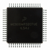
MC908MR32CFUE Freescale Semiconductor, MC908MR32CFUE Datasheet - Page 74

MC908MR32CFUE
Manufacturer Part Number
MC908MR32CFUE
Description
IC MCU 8MHZ 32K FLASH 64-QFP
Manufacturer
Freescale Semiconductor
Series
HC08r
Datasheet
1.MC908MR16CFUE.pdf
(282 pages)
Specifications of MC908MR32CFUE
Core Processor
HC08
Core Size
8-Bit
Speed
8MHz
Connectivity
SCI, SPI
Peripherals
LVD, POR, PWM
Number Of I /o
44
Program Memory Size
32KB (32K x 8)
Program Memory Type
FLASH
Ram Size
768 x 8
Voltage - Supply (vcc/vdd)
4.5 V ~ 5.5 V
Data Converters
A/D 10x10b
Oscillator Type
Internal
Operating Temperature
-40°C ~ 85°C
Package / Case
64-QFP
Processor Series
HC08MR
Core
HC08
Data Bus Width
8 bit
Data Ram Size
768 B
Interface Type
SCI/SPI
Maximum Clock Frequency
8.2 MHz
Number Of Programmable I/os
44
Number Of Timers
6
Operating Supply Voltage
0 V to 5 V
Maximum Operating Temperature
+ 85 C
Mounting Style
SMD/SMT
Development Tools By Supplier
FSICEBASE, M68CBL05CE
Minimum Operating Temperature
- 40 C
On-chip Adc
10-ch x 10-bit
Lead Free Status / RoHS Status
Lead free / RoHS Compliant
Eeprom Size
-
Lead Free Status / Rohs Status
Lead free / RoHS Compliant
Available stocks
Company
Part Number
Manufacturer
Quantity
Price
Company:
Part Number:
MC908MR32CFUE
Manufacturer:
Freescale Semiconductor
Quantity:
10 000
Part Number:
MC908MR32CFUE
Manufacturer:
NXP/恩智浦
Quantity:
20 000
- Current page: 74 of 282
- Download datasheet (2Mb)
Configuration Register (CONFIG)
5.3 Configuration Register
EDGE — Edge-Align Enable Bit
BOTNEG — Bottom-Side PWM Polarity Bit
TOPNEG — Top-Side PWM Polarity Bit
INDEP — Independent Mode Enable Bit
LVIRST — LVI Reset Enable Bit
LVIPWR — LVI Power Enable Bit
STOPE — Stop Enable Bit
COPD — COP Disable Bit
74
EDGE determines if the motor control PWM will operate in edge-aligned mode or center-aligned mode.
See
BOTNEG determines if the bottom-side PWMs will have positive or negative polarity. See
Pulse-Width Modulator for Motor Control
TOPNEG determines if the top-side PWMs will have positive or negative polarity. See
Pulse-Width Modulator for Motor Control
INDEP determines if the motor control PWMs will be six independent PWMs or three complementary
PWM pairs. See
LVIRST enables the reset signal from the LVI module. See
Chapter 9 Low-Voltage Inhibit
LVIPWR enables the LVI module.
Writing a 0 or a 1 to bit 1 has no effect on MCU operation. Bit 1 operates the same as the other bits
within this write-once register operate.
COPD disables the COP module. See
1 = Edge-aligned mode enabled
0 = Center-aligned mode enabled
1 = Negative polarity
0 = Positive polarity
1 = Negative polarity
0 = Positive polarity
1 = Six independent PWMs
0 = Three complementary PWM pairs
1 = LVI module resets enabled
0 = LVI module resets disabled
1 = LVI module power enabled
0 = LVI module power disabled
1 = STOP mode enabled
0 = STOP mode disabled
1 = COP module disabled
0 = COP module enabled
Chapter 12 Pulse-Width Modulator for Motor Control
Address:
Reset:
Read:
Write:
Chapter 12 Pulse-Width Modulator for Motor Control
$001F
EDGE
Bit 7
0
MC68HC908MR32 • MC68HC908MR16 Data Sheet, Rev. 6.1
Figure 5-1. Configuration Register (CONFIG)
BOTNEG
6
0
(LVI).
Chapter 9 Low-Voltage Inhibit (LVI)
TOPNEG
5
0
Chapter 6 Computer Operating Properly
(PWMMC).
(PWMMC).
INDEP
4
0
LVIRST
3
1
(PWMMC).
LVIPWR
2
1
(PWMMC).
STOPE
1
0
(COP).
Freescale Semiconductor
COPD
Bit 0
0
Chapter 12
Chapter 12
Related parts for MC908MR32CFUE
Image
Part Number
Description
Manufacturer
Datasheet
Request
R
Part Number:
Description:
Manufacturer:
Freescale Semiconductor, Inc
Datasheet:
Part Number:
Description:
Manufacturer:
Freescale Semiconductor, Inc
Datasheet:
Part Number:
Description:
Manufacturer:
Freescale Semiconductor, Inc
Datasheet:
Part Number:
Description:
Manufacturer:
Freescale Semiconductor, Inc
Datasheet:
Part Number:
Description:
Manufacturer:
Freescale Semiconductor, Inc
Datasheet:
Part Number:
Description:
Manufacturer:
Freescale Semiconductor, Inc
Datasheet:
Part Number:
Description:
Manufacturer:
Freescale Semiconductor, Inc
Datasheet:
Part Number:
Description:
Manufacturer:
Freescale Semiconductor, Inc
Datasheet:
Part Number:
Description:
Manufacturer:
Freescale Semiconductor, Inc
Datasheet:
Part Number:
Description:
Manufacturer:
Freescale Semiconductor, Inc
Datasheet:
Part Number:
Description:
Manufacturer:
Freescale Semiconductor, Inc
Datasheet:
Part Number:
Description:
Manufacturer:
Freescale Semiconductor, Inc
Datasheet:
Part Number:
Description:
Manufacturer:
Freescale Semiconductor, Inc
Datasheet:
Part Number:
Description:
Manufacturer:
Freescale Semiconductor, Inc
Datasheet:
Part Number:
Description:
Manufacturer:
Freescale Semiconductor, Inc
Datasheet:


