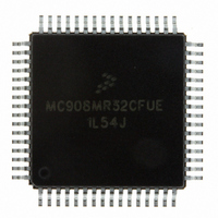
MC908MR32CFUE Freescale Semiconductor, MC908MR32CFUE Datasheet - Page 125

MC908MR32CFUE
Manufacturer Part Number
MC908MR32CFUE
Description
IC MCU 8MHZ 32K FLASH 64-QFP
Manufacturer
Freescale Semiconductor
Series
HC08r
Datasheet
1.MC908MR16CFUE.pdf
(282 pages)
Specifications of MC908MR32CFUE
Core Processor
HC08
Core Size
8-Bit
Speed
8MHz
Connectivity
SCI, SPI
Peripherals
LVD, POR, PWM
Number Of I /o
44
Program Memory Size
32KB (32K x 8)
Program Memory Type
FLASH
Ram Size
768 x 8
Voltage - Supply (vcc/vdd)
4.5 V ~ 5.5 V
Data Converters
A/D 10x10b
Oscillator Type
Internal
Operating Temperature
-40°C ~ 85°C
Package / Case
64-QFP
Processor Series
HC08MR
Core
HC08
Data Bus Width
8 bit
Data Ram Size
768 B
Interface Type
SCI/SPI
Maximum Clock Frequency
8.2 MHz
Number Of Programmable I/os
44
Number Of Timers
6
Operating Supply Voltage
0 V to 5 V
Maximum Operating Temperature
+ 85 C
Mounting Style
SMD/SMT
Development Tools By Supplier
FSICEBASE, M68CBL05CE
Minimum Operating Temperature
- 40 C
On-chip Adc
10-ch x 10-bit
Lead Free Status / RoHS Status
Lead free / RoHS Compliant
Eeprom Size
-
Lead Free Status / Rohs Status
Lead free / RoHS Compliant
Available stocks
Company
Part Number
Manufacturer
Quantity
Price
Company:
Part Number:
MC908MR32CFUE
Manufacturer:
Freescale Semiconductor
Quantity:
10 000
Part Number:
MC908MR32CFUE
Manufacturer:
NXP/恩智浦
Quantity:
20 000
- Current page: 125 of 282
- Download datasheet (2Mb)
12.4.2 PWM Data Overflow and Underflow Conditions
The PWM value registers are 16-bit registers. Although the counter is only 12 bits, the user may write a
16-bit signed value to a PWM value register. As shown in
is less than or equal to zero, the PWM will be inactive for the entire period. Conversely, if the PWM value
is greater than or equal to the timer modulus, the PWM will be active for the entire period. Refer to
Table
Freescale Semiconductor
12-3.
The terms “active” and “inactive” refer to the asserted and negated states
of the PWM signals and should not be confused with the high-impedance
state of the PWM pins.
PWMVALxH:PWMVALxL
COUNTER
Table 12-3. PWM Data Overflow and Underflow Conditions
UP-ONLY
$0000–$0FFF
$1000–$7FFF
$8000–$FFFF
PWM VALUE = 2
MODULUS = 3
PWM
PWMF SET
LDOK = 1
MC68HC908MR32 • MC68HC908MR16 Data Sheet, Rev. 6.1
Figure 12-11. Edge-Aligned Modulus Loading
PWM VALUE = 2
MODULUS = 4
PWMF SET
LDOK = 1
LDFQ1:LDFQ0 = 00 (RELOAD EVERY CYCLE)
Condition
Underflow
Overflow
NOTE
Normal
PWM VALUE = 2
Figure 12-4
MODULUS = 2
PWMF SET
LDOK = 1
Per register contents
and
PWM Value Used
PWM VALUE = 2
MODULUS = 1
PWMF SET
LDOK = 0
Figure
$FFF
$000
12-5, if the PWM value
PWM Generators
125
Related parts for MC908MR32CFUE
Image
Part Number
Description
Manufacturer
Datasheet
Request
R
Part Number:
Description:
Manufacturer:
Freescale Semiconductor, Inc
Datasheet:
Part Number:
Description:
Manufacturer:
Freescale Semiconductor, Inc
Datasheet:
Part Number:
Description:
Manufacturer:
Freescale Semiconductor, Inc
Datasheet:
Part Number:
Description:
Manufacturer:
Freescale Semiconductor, Inc
Datasheet:
Part Number:
Description:
Manufacturer:
Freescale Semiconductor, Inc
Datasheet:
Part Number:
Description:
Manufacturer:
Freescale Semiconductor, Inc
Datasheet:
Part Number:
Description:
Manufacturer:
Freescale Semiconductor, Inc
Datasheet:
Part Number:
Description:
Manufacturer:
Freescale Semiconductor, Inc
Datasheet:
Part Number:
Description:
Manufacturer:
Freescale Semiconductor, Inc
Datasheet:
Part Number:
Description:
Manufacturer:
Freescale Semiconductor, Inc
Datasheet:
Part Number:
Description:
Manufacturer:
Freescale Semiconductor, Inc
Datasheet:
Part Number:
Description:
Manufacturer:
Freescale Semiconductor, Inc
Datasheet:
Part Number:
Description:
Manufacturer:
Freescale Semiconductor, Inc
Datasheet:
Part Number:
Description:
Manufacturer:
Freescale Semiconductor, Inc
Datasheet:
Part Number:
Description:
Manufacturer:
Freescale Semiconductor, Inc
Datasheet:


