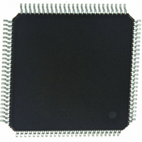
Z16F2811AL20SG Zilog, Z16F2811AL20SG Datasheet - Page 248

Z16F2811AL20SG
Manufacturer Part Number
Z16F2811AL20SG
Description
IC ZNEO MCU FLASH 128K 100LQFP
Manufacturer
Zilog
Series
Encore!® ZNEOr
Specifications of Z16F2811AL20SG
Core Processor
ZNEO
Core Size
16-Bit
Speed
20MHz
Connectivity
EBI/EMI, I²C, IrDA, LIN, SPI, UART/USART
Peripherals
Brown-out Detect/Reset, DMA, POR, PWM, WDT
Number Of I /o
76
Program Memory Size
128KB (128K x 8)
Program Memory Type
FLASH
Ram Size
4K x 8
Voltage - Supply (vcc/vdd)
2.7 V ~ 3.6 V
Data Converters
A/D 12x10b
Oscillator Type
Internal
Operating Temperature
0°C ~ 70°C
Package / Case
100-LQFP
Processor Series
Z16F2x
Core
Zneo
Data Bus Width
16 bit
Data Ram Size
4 B
Interface Type
ESPI, I2C, UART
Maximum Clock Frequency
20 MHz
Number Of Programmable I/os
76
Number Of Timers
4
Operating Supply Voltage
2.7 V to 3.6 V
Maximum Operating Temperature
+ 70 C
Mounting Style
SMD/SMT
Development Tools By Supplier
Z16F2800100ZCOG
Minimum Operating Temperature
0 C
On-chip Adc
10 bit, 12 Channel
For Use With
770-1003 - ISP 4PORT FOR ZILOG ZNEO MCU269-4537 - DEV KIT FOR Z16F ZNEO
Lead Free Status / RoHS Status
Lead free / RoHS Compliant
Eeprom Size
-
Lead Free Status / Rohs Status
Details
Other names
269-4533
Available stocks
Company
Part Number
Manufacturer
Quantity
Price
Company:
Part Number:
Z16F2811AL20SG
Manufacturer:
VISHAY
Quantity:
9 487
Part Number:
Z16F2811AL20SG
Manufacturer:
ZILOG
Quantity:
20 000
- Current page: 248 of 388
- Download datasheet (22Mb)
Table 114. I
BITS
FIELD
RESET
R/W
ADDR
PS022008-0810
2
C State Register (I2CSTATE) - Description when DIAG = 1
R
7
0
must not be written when
clears when transmission of the next byte begins or the transaction is ended by a STOP or
RESTART condition.
ACK—Acknowledge
This bit indicates the status of the Acknowledge for the last byte transmitted or received.
This bit is set for an Acknowledge and cleared for a Not Acknowledge condition.
AS—Address state
This bit is active High while the address is being transferred on the I
DS—Data state
This bit is active High while the data is being transferred on the I
10B—This bit indicates whether a 10 or 7-bit address is being transmitted when operating
as a Master. After the
11110B
RSTR—RESTART
This bit is updated each time a STOP or RESTART interrupt occurs (
I2CISTAT register).
0 = Stop condition
1 = Restart condition
SCLOUT—Serial Clock Output
Current value of Serial Clock being output onto the bus. The actual values of the SCL and
SDA signals on the I
BUSY—I
0 = No activity on the I
1 = A transaction is underway on the I
I2CSTATE_H—I
This field defines the current state of the I
the internal state machine.
I2CSTATE_L—Least significant nibble of the I
substates for the states defined by I2CSTATE_H.
for this field.
, this bit is set. When set, it is reset once the address has been sent.
2
C bus busy
R
6
I2CSTATE_H
0
2
C State
2
C bus is observed via the GPIO Input register.
START
R
2
5
0
C Bus.
TDRE
P R E L I M I N A R Y
Table 115
bit is set, if the five most-significant bits of the address are
asserts; instead, software waits for
R
4
0
FF-E245H
on page 233 defines the states for this field.
2
C bus.
2
C Controller. It is the most significant nibble of
R
3
0
2
Table 116
C state machine. This field defines the
on page 234 defines the values
R
2
0
I2CSTATE_L
I
2
C Master/Slave Controller
Product Specification
2
C bus.
ACKV
ZNEO
2
SPRS
C bus.
R
1
0
to assert. This bit
bit set in
Z16F Series
R
0
0
232
Related parts for Z16F2811AL20SG
Image
Part Number
Description
Manufacturer
Datasheet
Request
R

Part Number:
Description:
High Performance Microcontrollers
Manufacturer:
ZiLOG Semiconductor
Datasheet:

Part Number:
Description:
Communication Controllers, ZILOG INTELLIGENT PERIPHERAL CONTROLLER (ZIP)
Manufacturer:
Zilog, Inc.
Datasheet:

Part Number:
Description:
KIT DEV FOR Z8 ENCORE 16K TO 64K
Manufacturer:
Zilog
Datasheet:

Part Number:
Description:
KIT DEV Z8 ENCORE XP 28-PIN
Manufacturer:
Zilog
Datasheet:

Part Number:
Description:
DEV KIT FOR Z8 ENCORE 8K/4K
Manufacturer:
Zilog
Datasheet:

Part Number:
Description:
KIT DEV Z8 ENCORE XP 28-PIN
Manufacturer:
Zilog
Datasheet:

Part Number:
Description:
DEV KIT FOR Z8 ENCORE 4K TO 8K
Manufacturer:
Zilog
Datasheet:

Part Number:
Description:
CMOS Z8 microcontroller. ROM 16 Kbytes, RAM 256 bytes, speed 16 MHz, 32 lines I/O, 3.0V to 5.5V
Manufacturer:
Zilog, Inc.
Datasheet:

Part Number:
Description:
Low-cost microcontroller. 512 bytes ROM, 61 bytes RAM, 8 MHz
Manufacturer:
Zilog, Inc.
Datasheet:

Part Number:
Description:
Z8 4K OTP Microcontroller
Manufacturer:
Zilog, Inc.
Datasheet:

Part Number:
Description:
CMOS SUPER8 ROMLESS MCU
Manufacturer:
Zilog, Inc.
Datasheet:

Part Number:
Description:
SL1866 CMOSZ8 OTP Microcontroller
Manufacturer:
Zilog, Inc.
Datasheet:

Part Number:
Description:
SL1866 CMOSZ8 OTP Microcontroller
Manufacturer:
Zilog, Inc.
Datasheet:

Part Number:
Description:
OTP (KB) = 1, RAM = 125, Speed = 12, I/O = 14, 8-bit Timers = 2, Comm Interfaces Other Features = Por, LV Protect, Voltage = 4.5-5.5V
Manufacturer:
Zilog, Inc.
Datasheet:


