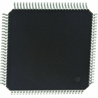
Z16F2811AL20SG Zilog, Z16F2811AL20SG Datasheet - Page 161

Z16F2811AL20SG
Manufacturer Part Number
Z16F2811AL20SG
Description
IC ZNEO MCU FLASH 128K 100LQFP
Manufacturer
Zilog
Series
Encore!® ZNEOr
Specifications of Z16F2811AL20SG
Core Processor
ZNEO
Core Size
16-Bit
Speed
20MHz
Connectivity
EBI/EMI, I²C, IrDA, LIN, SPI, UART/USART
Peripherals
Brown-out Detect/Reset, DMA, POR, PWM, WDT
Number Of I /o
76
Program Memory Size
128KB (128K x 8)
Program Memory Type
FLASH
Ram Size
4K x 8
Voltage - Supply (vcc/vdd)
2.7 V ~ 3.6 V
Data Converters
A/D 12x10b
Oscillator Type
Internal
Operating Temperature
0°C ~ 70°C
Package / Case
100-LQFP
Processor Series
Z16F2x
Core
Zneo
Data Bus Width
16 bit
Data Ram Size
4 B
Interface Type
ESPI, I2C, UART
Maximum Clock Frequency
20 MHz
Number Of Programmable I/os
76
Number Of Timers
4
Operating Supply Voltage
2.7 V to 3.6 V
Maximum Operating Temperature
+ 70 C
Mounting Style
SMD/SMT
Development Tools By Supplier
Z16F2800100ZCOG
Minimum Operating Temperature
0 C
On-chip Adc
10 bit, 12 Channel
For Use With
770-1003 - ISP 4PORT FOR ZILOG ZNEO MCU269-4537 - DEV KIT FOR Z16F ZNEO
Lead Free Status / RoHS Status
Lead free / RoHS Compliant
Eeprom Size
-
Lead Free Status / Rohs Status
Details
Other names
269-4533
Available stocks
Company
Part Number
Manufacturer
Quantity
Price
Company:
Part Number:
Z16F2811AL20SG
Manufacturer:
VISHAY
Quantity:
9 487
Part Number:
Z16F2811AL20SG
Manufacturer:
ZILOG
Quantity:
20 000
- Current page: 161 of 388
- Download datasheet (22Mb)
®
ZNEO
Z16F Series
Product Specification
145
In addition to the LMST, LSLV, and ABEN bits in the LIN control register, a LinState[1:0]
field exists that defines the current state of the LIN logic. This field is initially set by the
software. In the LIN SLAVE mode, the LinState field is updated by hardware as the slave
moves through the Wait for Break, AutoBaud, and Active states.
The noise filter is also required to be enabled and configured when interfacing to
a LIN bus.
LIN MASTER Mode Operation
LIN MASTER mode is selected by setting the bits LMST = 1, LSLV = 0, ABEN = 0,
LinState[1:0] = 11b. If the LIN bus protocol indicates the bus is required go into the LIN
Sleep state, the LinState[1:0] bits must be set =
by the software.
00b
The Break is the first part of the message frame transmitted by the master, consisting of at
least 13 bit periods of logical zero on the LIN bus. During initialization of the LIN master,
the duration (in bit times) of the Break is written to the TxBreakLength field of the LIN
control register. The transmission of the Break is performed by setting the
bit in the
SBRK
control 0 register. The LIN-UART starts the Break once the
bit is set and any
SBRK
character transmission currently underway has completed. The
bit is deasserted by
SBRK
hardware once the break is completed.
The Synch character is transmitted by writing a
to the transmit data register (
55H
TDRE
must be 1 before writing). The Synch character is not transmitted by the hardware until
after the Break is complete.
The Identifier character is transmitted by writing the appropriate value to the transmit data
register (
must be 1 before writing).
TDRE
If the master is sending the response portion of the message, these data and checksum
characters are written to the transmit data register when the TDRE bit asserts.
If the transmit data register is written after TDRE asserts, but before TXE asserts, the
hardware inserts one or two Stop bits between each character as determined by the Stop bit
in the control0 register. Additional idle time occurs between characters if TXE asserts
before the next character is written.
LIN Sleep Mode
While the LIN bus is in the Sleep state, the CPU is in either low power STOP mode, in
HALT mode, or in normal operational state. Any device on the LIN bus issues a Wake-up
message (transmit an
character) if it needs the master to initiate a LIN message frame.
80H
Following the Wake-up message, the master wakes up and initiates a new message.
If the CPU is in STOP mode, the LIN-UART is not active and the Wake-up message must
be detected by a GPIO edge detect Stop Mode Recovery. The duration of the Stop Mode
Recovery sequence may preclude making an accurate measurement of the Wake-up
message duration.
PS022008-0810
P R E L I M I N A R Y
LIN-UART
Related parts for Z16F2811AL20SG
Image
Part Number
Description
Manufacturer
Datasheet
Request
R

Part Number:
Description:
High Performance Microcontrollers
Manufacturer:
ZiLOG Semiconductor
Datasheet:

Part Number:
Description:
Communication Controllers, ZILOG INTELLIGENT PERIPHERAL CONTROLLER (ZIP)
Manufacturer:
Zilog, Inc.
Datasheet:

Part Number:
Description:
KIT DEV FOR Z8 ENCORE 16K TO 64K
Manufacturer:
Zilog
Datasheet:

Part Number:
Description:
KIT DEV Z8 ENCORE XP 28-PIN
Manufacturer:
Zilog
Datasheet:

Part Number:
Description:
DEV KIT FOR Z8 ENCORE 8K/4K
Manufacturer:
Zilog
Datasheet:

Part Number:
Description:
KIT DEV Z8 ENCORE XP 28-PIN
Manufacturer:
Zilog
Datasheet:

Part Number:
Description:
DEV KIT FOR Z8 ENCORE 4K TO 8K
Manufacturer:
Zilog
Datasheet:

Part Number:
Description:
CMOS Z8 microcontroller. ROM 16 Kbytes, RAM 256 bytes, speed 16 MHz, 32 lines I/O, 3.0V to 5.5V
Manufacturer:
Zilog, Inc.
Datasheet:

Part Number:
Description:
Low-cost microcontroller. 512 bytes ROM, 61 bytes RAM, 8 MHz
Manufacturer:
Zilog, Inc.
Datasheet:

Part Number:
Description:
Z8 4K OTP Microcontroller
Manufacturer:
Zilog, Inc.
Datasheet:

Part Number:
Description:
CMOS SUPER8 ROMLESS MCU
Manufacturer:
Zilog, Inc.
Datasheet:

Part Number:
Description:
SL1866 CMOSZ8 OTP Microcontroller
Manufacturer:
Zilog, Inc.
Datasheet:

Part Number:
Description:
SL1866 CMOSZ8 OTP Microcontroller
Manufacturer:
Zilog, Inc.
Datasheet:

Part Number:
Description:
OTP (KB) = 1, RAM = 125, Speed = 12, I/O = 14, 8-bit Timers = 2, Comm Interfaces Other Features = Por, LV Protect, Voltage = 4.5-5.5V
Manufacturer:
Zilog, Inc.
Datasheet:


