5.07.01 FLASHER ARM Segger Microcontroller Systems, 5.07.01 FLASHER ARM Datasheet - Page 46
5.07.01 FLASHER ARM
Manufacturer Part Number
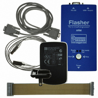
5.07.01 FLASHER ARM
Description
PROGRAMMER JTAG FOR ARM CORES
Manufacturer
Segger Microcontroller Systems
Type
In-System Programmerr
Specifications of 5.07.01 FLASHER ARM
Contents
Programmer
For Use With/related Products
ARM7, ARM9, Cortex
Lead Free Status / RoHS Status
Lead free / RoHS Compliant
Other names
899-1002


46
5.4
5.4.1
5.4.2
Flasher ARM (UM08007)
The J-Link JTAG Isolator can be connected between J-Link ARM
and any ARMboard that uses the standard 20-pin JTAG-ARM
connector to provide electrical isolation. This is essential when
the development tools are not connected to the same ground
as the application. For more information about the J-Link JTAG
Isolator, please refer to J-Link JTAG Isolator User Manual
(UM08010) which can be downloaded from our website.
The following table shows the target-side pinout of the J-Link
JTAG Isolator.
Table 5.4:
Pins 4, 6, 8, 10, 12, 14, 16, 18, 20 are GND pins connected to GND.
1
2
3
5
7
9
11
13
15
17
19
Pin
Adapters
J-Link JTAG Isolator
Pinout
VCC
VCC
nTRST
TDI
TMS
TCK
RTCK
TDO
RESET
N/C
N/C
Signal
Output
Output
Output
Output
Output
Output
Input
Input
I/O
N/C
N/C
Type
The target side of the isolator draws power over this pin.
The target side of the isolator draws power over this pin.
JTAG Reset. Output from Flasher ARM to the Reset signal
of the target JTAG port. Typically connected to nTRST of
the target CPU. This pin is normally pulled HIGH on the
target to avoid unintentional resets when there is no con-
nection.
JTAG data input of target CPU. It is recommended that
this pin is pulled to a defined state on the target board.
Typically connected to TDI of target CPU.
JTAG mode set input of target CPU. This pin should be
pulled up on the target. Typically connected to TMS of
target CPU.
JTAG clock signal to target CPU. It is recommended that
this pin is pulled to a defined state of the target board.
Typically connected to TCK of target CPU.
Return test clock signal from the target. Some targets
must synchronize the JTAG inputs to internal clocks. To
assist in meeting this requirement, you can use a
returned, and retimed, TCK to dynamically control the
TCK rate. Flasher ARM supports adaptive clocking, which
waits for TCK changes to be echoed correctly before mak-
ing further changes. Connect to RTCK if available, other-
wise to GND.
JTAG data output from target CPU. Typically connected to
TDO of target CPU.
Target CPU reset signal. Typically connected to the RESET
pin of the target CPU, which is typically called "nRST",
"nRESET" or "RESET".
This pin is not connected on the target side of the isola-
tor.
This pin is not connected on the target side of the isola-
tor.
CHAPTER 5
© 2004-2009 SEGGER Microcontroller GmbH & Co. KG
Description
VCC
nTRST
TDI
TMS
TCK
RTCK
TDO
RESET
N/C
N/C
11
13
15
17
19
5
1
3
7
9
10
12
14
16
18
20
4
6
8
2
GND
GND
GND
GND
VCC
GND
GND
GND
GND
GND
Hardware
Related parts for 5.07.01 FLASHER ARM
Image
Part Number
Description
Manufacturer
Datasheet
Request
R

Part Number:
Description:
CONNECTOR JTAG-ARM ISOLATION
Manufacturer:
Segger Microcontroller Systems
Datasheet:

Part Number:
Description:
ADAPTER ARM TARGET 14PIN RIBBON
Manufacturer:
Segger Microcontroller Systems
Datasheet:

Part Number:
Description:
JTAG EMULATOR FOR ARM CORES
Manufacturer:
Segger Microcontroller Systems
Datasheet:

Part Number:
Description:
JTAG EMULATOR FOR ARM CORES
Manufacturer:
Segger Microcontroller Systems
Datasheet:

Part Number:
Description:
PROGRAMMING TOOL FOR MCU
Manufacturer:
Segger Microcontroller Systems
Datasheet:

Part Number:
Description:
PROGRAMMING TOOL FOR ST7 MCU
Manufacturer:
Segger Microcontroller Systems
Datasheet:

Part Number:
Description:
PROGRAMMING TOOL FOR STM8
Manufacturer:
Segger Microcontroller Systems
Datasheet:

Part Number:
Description:
JTAG EMULATOR USB ETHERNET ARM
Manufacturer:
Segger Microcontroller Systems
Datasheet:

Part Number:
Description:
JTAG EMULATOR ARM7/ARM9 ETM
Manufacturer:
Segger Microcontroller Systems
Datasheet:

Part Number:
Description:
EMULATOR JTAG/SWD CORTEX M3
Manufacturer:
Segger Microcontroller Systems
Datasheet: