C8051F411EK Silicon Laboratories Inc, C8051F411EK Datasheet - Page 173
C8051F411EK
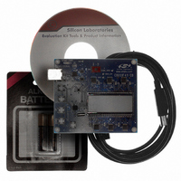
Manufacturer Part Number
C8051F411EK
Description
KIT EVAL FOR C8051F411
Manufacturer
Silicon Laboratories Inc
Type
MCUr
Specifications of C8051F411EK
Contents
Evaluation Board, CD-ROM, USB Cable, Batteries and User Guide
Processor To Be Evaluated
C8051F41x
Interface Type
USB
Silicon Manufacturer
Silicon Labs
Core Architecture
8051
Silicon Core Number
C8051F411
Silicon Family Name
C8051F41x
Kit Contents
LCD Based Evaluation Board, USB Cable, Software CD And Quick-Start Guide
Lead Free Status / RoHS Status
Contains lead / RoHS non-compliant
For Use With/related Products
Silicon Laboratories C8051F41x
For Use With
336-1315 - KIT REF DESIGN VOICE RECORD F41X
Lead Free Status / Rohs Status
Lead free / RoHS Compliant
Other names
336-1317


Note:
Bit7:
Bit6:
Bit5:
Bits4–2: MULDIV: Clock Multiplier Output Scaling Factor
Bits1–0: MULSEL: Clock Multiplier Input Select
MULEN
R/W
Bit7
The maximum SYSCLK is 50 MHz, so the Clock Multiplier output should be scaled accord-
ingly.
MULEN: Clock Multiplier Enable
0: Clock Multiplier disabled.
1: Clock Multiplier enabled.
MULINIT: Clock Multiplier Initialize
This bit should be a ‘0’ when the Clock Multiplier is enabled. Once enabled, writing a ‘1’ to
this bit will initialize the Clock Multiplier. The MULRDY bit reads ‘1’ when the Clock Multiplier
is stabilized.
MULRDY: Clock Multiplier Ready
This read-only bit indicates the status of the Clock Multiplier.
0: Clock Multiplier not ready.
1: Clock Multiplier ready (locked).
These bits scale the Clock Multiplier output.
000: Clock Multiplier Output scaled by a factor of 1.
001: Clock Multiplier Output scaled by a factor of 1.
010: Clock Multiplier Output scaled by a factor of 1.
011: Clock Multiplier Output scaled by a factor of 2/3*.
100: Clock Multiplier Output scaled by a factor of 2/4 (or 1/2).
101: Clock Multiplier Output scaled by a factor of 2/5*.
110: Clock Multiplier Output scaled by a factor of 2/6 (or 1/3).
111: Clock Multiplier Output scaled by a factor of 2/7*.
These bits select the clock supplied to the Clock Multiplier.
*Note: The Clock Multiplier Output duty cycle is not 50% for these settings.
MULINIT MULRDY
R/W
Bit6
SFR Definition 19.4. CLKMUL: Clock Multiplier Control
MULSEL
00
01
10
11
Bit5
R
R/W
Bit4
Selected Input Clock
External Oscillator / 2
Internal Oscillator / 2
External Oscillator
Internal Oscillator
MULDIV
Rev. 1.1
R/W
Bit3
R/W
Bit2
C8051F410/1/2/3
Clock Multiplier Output
External Oscillator x 4
External Oscillator x 2
R/W
Internal Oscillator x 2
Internal Oscillator x 4
Bit1
for MULDIV = 000b
MULSEL
SFR Address:
R/W
Bit0
0xAB
00000000
Reset Value
173
Related parts for C8051F411EK
Image
Part Number
Description
Manufacturer
Datasheet
Request
R

Part Number:
Description:
SMD/C°/SINGLE-ENDED OUTPUT SILICON OSCILLATOR
Manufacturer:
Silicon Laboratories Inc
Part Number:
Description:
Manufacturer:
Silicon Laboratories Inc
Datasheet:
Part Number:
Description:
N/A N/A/SI4010 AES KEYFOB DEMO WITH LCD RX
Manufacturer:
Silicon Laboratories Inc
Datasheet:
Part Number:
Description:
N/A N/A/SI4010 SIMPLIFIED KEY FOB DEMO WITH LED RX
Manufacturer:
Silicon Laboratories Inc
Datasheet:
Part Number:
Description:
N/A/-40 TO 85 OC/EZLINK MODULE; F930/4432 HIGH BAND (REV E/B1)
Manufacturer:
Silicon Laboratories Inc
Part Number:
Description:
EZLink Module; F930/4432 Low Band (rev e/B1)
Manufacturer:
Silicon Laboratories Inc
Part Number:
Description:
I°/4460 10 DBM RADIO TEST CARD 434 MHZ
Manufacturer:
Silicon Laboratories Inc
Part Number:
Description:
I°/4461 14 DBM RADIO TEST CARD 868 MHZ
Manufacturer:
Silicon Laboratories Inc
Part Number:
Description:
I°/4463 20 DBM RFSWITCH RADIO TEST CARD 460 MHZ
Manufacturer:
Silicon Laboratories Inc
Part Number:
Description:
I°/4463 20 DBM RADIO TEST CARD 868 MHZ
Manufacturer:
Silicon Laboratories Inc
Part Number:
Description:
I°/4463 27 DBM RADIO TEST CARD 868 MHZ
Manufacturer:
Silicon Laboratories Inc
Part Number:
Description:
I°/4463 SKYWORKS 30 DBM RADIO TEST CARD 915 MHZ
Manufacturer:
Silicon Laboratories Inc
Part Number:
Description:
N/A N/A/-40 TO 85 OC/4463 RFMD 30 DBM RADIO TEST CARD 915 MHZ
Manufacturer:
Silicon Laboratories Inc
Part Number:
Description:
I°/4463 20 DBM RADIO TEST CARD 169 MHZ
Manufacturer:
Silicon Laboratories Inc