C8051F411EK Silicon Laboratories Inc, C8051F411EK Datasheet - Page 170
C8051F411EK
Manufacturer Part Number
C8051F411EK
Description
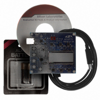
KIT EVAL FOR C8051F411
Manufacturer
Silicon Laboratories Inc
Type
MCUr
Specifications of C8051F411EK
Contents
Evaluation Board, CD-ROM, USB Cable, Batteries and User Guide
Processor To Be Evaluated
C8051F41x
Interface Type
USB
Silicon Manufacturer
Silicon Labs
Core Architecture
8051
Silicon Core Number
C8051F411
Silicon Family Name
C8051F41x
Kit Contents
LCD Based Evaluation Board, USB Cable, Software CD And Quick-Start Guide
Lead Free Status / RoHS Status
Contains lead / RoHS non-compliant
For Use With/related Products
Silicon Laboratories C8051F41x
For Use With
336-1315 - KIT REF DESIGN VOICE RECORD F41X
Lead Free Status / Rohs Status
Lead free / RoHS Compliant
Other names
336-1317


C8051F410/1/2/3
19.2.3. External RC Example
If an RC network is used as an external oscillator source for the MCU, the circuit should be configured as
shown in Figure 19.1, Option 2. The capacitor should be no greater than 100 pF; however for very small
capacitors, the total capacitance may be dominated by parasitic capacitance in the PCB layout. To deter-
mine the required External Oscillator Frequency Control value (XFCN) in the OSCXCN Register, first
select the RC network value to produce the desired frequency of oscillation. If the frequency desired is
100 kHz, let R = 246 k and C = 50 pF:
3
3
f = 1.23( 10
) / RC = 1.23 ( 10
) / [ 246 x 50 ] = 0.1 MHz = 100 kHz
Referring to the table in SFR Definition 19.3, the required XFCN setting is 010b. Programming XFCN to a
higher setting in RC mode will improve frequency accuracy at a slightly increased external oscillator supply
current.
19.2.4. External Capacitor Example
If a capacitor is used as an external oscillator for the MCU, the circuit should be configured as shown in
Figure 19.1, Option 3. The capacitor should be no greater than 100 pF; however for very small capacitors,
the total capacitance may be dominated by parasitic capacitance in the PCB layout. To determine the
required External Oscillator Frequency Control value (XFCN) in the OSCXCN Register, select the fre-
quency of oscillation and calculate the capacitance to be used from the equations below. Assume
V
= 2.0 V and f = 75 kHz:
DD
f = KF / (C x V
)
DD
0.075 MHz = KF / (C x 2.0)
Since the frequency of roughly 75 kHz is desired, select the K Factor from the table in SFR Definition 19.3
as KF = 7.7:
0.075 MHz = 7.7 / (C x 2.0)
C x 2.0 = 7.7 / 0.075 MHz
C = 102.6 / 2.0 pF = 51.3 pF
Therefore, the XFCN value to use in this example is 010b.
170
Rev. 1.1
Related parts for C8051F411EK
Image
Part Number
Description
Manufacturer
Datasheet
Request
R

Part Number:
Description:
SMD/C°/SINGLE-ENDED OUTPUT SILICON OSCILLATOR
Manufacturer:
Silicon Laboratories Inc
Part Number:
Description:
Manufacturer:
Silicon Laboratories Inc
Datasheet:
Part Number:
Description:
N/A N/A/SI4010 AES KEYFOB DEMO WITH LCD RX
Manufacturer:
Silicon Laboratories Inc
Datasheet:
Part Number:
Description:
N/A N/A/SI4010 SIMPLIFIED KEY FOB DEMO WITH LED RX
Manufacturer:
Silicon Laboratories Inc
Datasheet:
Part Number:
Description:
N/A/-40 TO 85 OC/EZLINK MODULE; F930/4432 HIGH BAND (REV E/B1)
Manufacturer:
Silicon Laboratories Inc
Part Number:
Description:
EZLink Module; F930/4432 Low Band (rev e/B1)
Manufacturer:
Silicon Laboratories Inc
Part Number:
Description:
I°/4460 10 DBM RADIO TEST CARD 434 MHZ
Manufacturer:
Silicon Laboratories Inc
Part Number:
Description:
I°/4461 14 DBM RADIO TEST CARD 868 MHZ
Manufacturer:
Silicon Laboratories Inc
Part Number:
Description:
I°/4463 20 DBM RFSWITCH RADIO TEST CARD 460 MHZ
Manufacturer:
Silicon Laboratories Inc
Part Number:
Description:
I°/4463 20 DBM RADIO TEST CARD 868 MHZ
Manufacturer:
Silicon Laboratories Inc
Part Number:
Description:
I°/4463 27 DBM RADIO TEST CARD 868 MHZ
Manufacturer:
Silicon Laboratories Inc
Part Number:
Description:
I°/4463 SKYWORKS 30 DBM RADIO TEST CARD 915 MHZ
Manufacturer:
Silicon Laboratories Inc
Part Number:
Description:
N/A N/A/-40 TO 85 OC/4463 RFMD 30 DBM RADIO TEST CARD 915 MHZ
Manufacturer:
Silicon Laboratories Inc
Part Number:
Description:
I°/4463 20 DBM RADIO TEST CARD 169 MHZ
Manufacturer:
Silicon Laboratories Inc