DEMO9S08EL32 Freescale Semiconductor, DEMO9S08EL32 Datasheet - Page 64
DEMO9S08EL32
Manufacturer Part Number
DEMO9S08EL32
Description
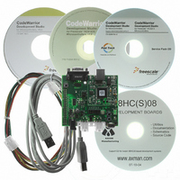
BOARD DEMO FOR 9S08 EL MCU
Manufacturer
Freescale Semiconductor
Type
MCUr
Datasheets
1.DEMO9S08EL32.pdf
(356 pages)
2.DEMO9S08EL32.pdf
(14 pages)
3.DEMO9S08EL32.pdf
(2 pages)
Specifications of DEMO9S08EL32
Contents
Evaluation Board
Processor To Be Evaluated
MC9S08EL32
Data Bus Width
8 bit
Interface Type
RS-232, USB
Operating Supply Voltage
12 V
Silicon Manufacturer
Freescale
Core Architecture
HCS08
Core Sub-architecture
HCS08
Silicon Core Number
MC9S08
Silicon Family Name
S08EL
Rohs Compliant
Yes
For Use With/related Products
MC9S08EL32
Lead Free Status / RoHS Status
Lead free / RoHS Compliant


Chapter 5 Resets, Interrupts, and General System Control
5.4
The COP watchdog is intended to force a system reset when the application software fails to execute as
expected. To prevent a system reset from the COP timer (when it is enabled), application software must
reset the COP counter periodically. If the application program gets lost and fails to reset the COP counter
before it times out, a system reset is generated to force the system back to a known starting point.
After any reset, the COP watchdog is enabled (see
for additional information). If the COP watchdog is not used in an application, it can be disabled by
clearing COPT bits in SOPT1.
The COP counter is reset by writing 0x0055 and 0x00AA (in this order) to the address of SRS during the
selected timeout period. Writes do not affect the data in the read-only SRS. As soon as the write sequence
is done, the COP timeout period is restarted. If the program fails to do this during the time-out period, the
MCU will reset. Also, if any value other than 0x0055 or 0x00AA is written to SRS, the MCU is
immediately reset.
The COPCLKS bit in SOPT2 (see
information) selects the clock source used for the COP timer. The clock source options are either the bus
clock or an internal 1-kHz clock source. With each clock source, there are three associated time-outs
controlled by the COPT bits in SOPT1.
COPT bits. The COP watchdog defaults to operation from the 1-kHz clock source and the longest time-out
(2
When the bus clock source is selected, windowed COP operation is available by setting COPW in the
SOPT2 register. In this mode, writes to the SRS register to clear the COP timer must occur in the last 25%
of the selected timeout period. A premature write immediately resets the MCU. When the 1-kHz clock
source is selected, windowed COP operation is not available.
64
10
cycles).
Computer Operating Properly (COP) Watchdog
1
Values are shown in this column based on t
A.12.1, “Control
COPCLKS
N/A
0
0
0
1
1
1
MC9S08EL32 Series and MC9S08SL16 Series Data Sheet, Rev. 3
Control Bits
Timing,” for the tolerance of this value.
Table 5-1. COP Configuration Options
COPT[1:0]
Section 5.7.4, “System Options Register 2
0:0
0:1
1:0
1:1
0:1
1:0
1:1
Table 5-1
Clock Source
summaries the control functions of the COPCLKS and
Section 5.7.3, “System Options Register 1
1 kHz
1 kHz
1 kHz
RTI
N/A
Bus
Bus
Bus
= 1 ms. See t
RTI
COP Overflow Count
2
2
2
10
8
5
in the appendix
COP is disabled
cycles (256 ms
cycles (32 ms
cycles (1.024 s
2
2
2
13
16
18
cycles
cycles
cycles
(SOPT2),” for additional
1
Section
1
)
1
)
Freescale Semiconductor
)
(SOPT1),”
Related parts for DEMO9S08EL32
Image
Part Number
Description
Manufacturer
Datasheet
Request
R

Part Number:
Description:
Manufacturer:
Freescale Semiconductor, Inc
Datasheet:
Part Number:
Description:
Manufacturer:
Freescale Semiconductor, Inc
Datasheet:
Part Number:
Description:
Manufacturer:
Freescale Semiconductor, Inc
Datasheet:
Part Number:
Description:
Manufacturer:
Freescale Semiconductor, Inc
Datasheet:
Part Number:
Description:
Manufacturer:
Freescale Semiconductor, Inc
Datasheet:
Part Number:
Description:
Manufacturer:
Freescale Semiconductor, Inc
Datasheet:
Part Number:
Description:
Manufacturer:
Freescale Semiconductor, Inc
Datasheet:
Part Number:
Description:
Manufacturer:
Freescale Semiconductor, Inc
Datasheet:
Part Number:
Description:
Manufacturer:
Freescale Semiconductor, Inc
Datasheet:
Part Number:
Description:
Manufacturer:
Freescale Semiconductor, Inc
Datasheet:
Part Number:
Description:
Manufacturer:
Freescale Semiconductor, Inc
Datasheet:
Part Number:
Description:
Manufacturer:
Freescale Semiconductor, Inc
Datasheet:
Part Number:
Description:
Manufacturer:
Freescale Semiconductor, Inc
Datasheet:
Part Number:
Description:
Manufacturer:
Freescale Semiconductor, Inc
Datasheet:
Part Number:
Description:
Manufacturer:
Freescale Semiconductor, Inc
Datasheet: