DEMO9S08EL32 Freescale Semiconductor, DEMO9S08EL32 Datasheet - Page 23
DEMO9S08EL32
Manufacturer Part Number
DEMO9S08EL32
Description
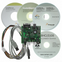
BOARD DEMO FOR 9S08 EL MCU
Manufacturer
Freescale Semiconductor
Type
MCUr
Datasheets
1.DEMO9S08EL32.pdf
(356 pages)
2.DEMO9S08EL32.pdf
(14 pages)
3.DEMO9S08EL32.pdf
(2 pages)
Specifications of DEMO9S08EL32
Contents
Evaluation Board
Processor To Be Evaluated
MC9S08EL32
Data Bus Width
8 bit
Interface Type
RS-232, USB
Operating Supply Voltage
12 V
Silicon Manufacturer
Freescale
Core Architecture
HCS08
Core Sub-architecture
HCS08
Silicon Core Number
MC9S08
Silicon Family Name
S08EL
Rohs Compliant
Yes
For Use With/related Products
MC9S08EL32
Lead Free Status / RoHS Status
Lead free / RoHS Compliant


EXTAL
* The fixed frequency clock (FFCLK) is internally
synchronized to the bus clock and must not exceed one
half of the bus clock frequency.
1.3
Figure 1-3
inputs as shown. The clock inputs to the modules indicate the clock(s) that are used to drive the module
function.
The following defines the clocks used in this MCU:
Freescale Semiconductor
XOSC
1 kHZ
LPO
ICS
•
•
•
•
•
•
•
•
XTAL
BUSCLK — The frequency of the bus is always half of ICSOUT.
ICSOUT — Primary output of the ICS and is twice the bus frequency.
ICSLCLK — Development tools can select this clock source to speed up BDC communications in
systems where the bus clock is configured to run at a very slow frequency.
ICSERCLK — External reference clock can be selected as the RTC clock source and as the
alternate clock for the ADC module.
ICSIRCLK — Internal reference clock can be selected as the RTC clock source.
ICSFFCLK — Fixed frequency clock can be selected as clock source for the TPM1 and TPM2
modules.
LPO — Independent 1-kHz clock that can be selected as the source for the COP and RTC modules.
TCLK — External input clock source for TPM1 and TPM2 and is referenced as TPMCLK in TPM
chapters.
System Clock Distribution
ICSERCLK
ICSIRCLK
ICSFFCLK
ICSOUT
ICSLCLK
shows a simplified clock connection diagram. Some modules in the MCU have selectable clock
CPU
÷
÷
2
2
MC9S08EL32 Series and MC9S08SL16 Series Data Sheet, Rev. 3
BUSCLK
Figure 1-3. System Clock Distribution Diagram
RTC
COP
TCLK
BDC
TPM1
FFCLK*
TPM2
ADC has min and max
frequency requirements.
See the ADC chapter
and electricals appendix
for details.
ADC
SCI
IIC
SLIC
Chapter 1 Device Overview
FLASH and EEPROM
have frequency
requirements for program
and erase operation. See
the electricals appendix
for details.
FLASH
SPI
EEPROM
23
Related parts for DEMO9S08EL32
Image
Part Number
Description
Manufacturer
Datasheet
Request
R

Part Number:
Description:
Manufacturer:
Freescale Semiconductor, Inc
Datasheet:
Part Number:
Description:
Manufacturer:
Freescale Semiconductor, Inc
Datasheet:
Part Number:
Description:
Manufacturer:
Freescale Semiconductor, Inc
Datasheet:
Part Number:
Description:
Manufacturer:
Freescale Semiconductor, Inc
Datasheet:
Part Number:
Description:
Manufacturer:
Freescale Semiconductor, Inc
Datasheet:
Part Number:
Description:
Manufacturer:
Freescale Semiconductor, Inc
Datasheet:
Part Number:
Description:
Manufacturer:
Freescale Semiconductor, Inc
Datasheet:
Part Number:
Description:
Manufacturer:
Freescale Semiconductor, Inc
Datasheet:
Part Number:
Description:
Manufacturer:
Freescale Semiconductor, Inc
Datasheet:
Part Number:
Description:
Manufacturer:
Freescale Semiconductor, Inc
Datasheet:
Part Number:
Description:
Manufacturer:
Freescale Semiconductor, Inc
Datasheet:
Part Number:
Description:
Manufacturer:
Freescale Semiconductor, Inc
Datasheet:
Part Number:
Description:
Manufacturer:
Freescale Semiconductor, Inc
Datasheet:
Part Number:
Description:
Manufacturer:
Freescale Semiconductor, Inc
Datasheet:
Part Number:
Description:
Manufacturer:
Freescale Semiconductor, Inc
Datasheet: