DEMO9S08EL32 Freescale Semiconductor, DEMO9S08EL32 Datasheet - Page 217
DEMO9S08EL32
Manufacturer Part Number
DEMO9S08EL32
Description
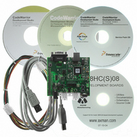
BOARD DEMO FOR 9S08 EL MCU
Manufacturer
Freescale Semiconductor
Type
MCUr
Datasheets
1.DEMO9S08EL32.pdf
(356 pages)
2.DEMO9S08EL32.pdf
(14 pages)
3.DEMO9S08EL32.pdf
(2 pages)
Specifications of DEMO9S08EL32
Contents
Evaluation Board
Processor To Be Evaluated
MC9S08EL32
Data Bus Width
8 bit
Interface Type
RS-232, USB
Operating Supply Voltage
12 V
Silicon Manufacturer
Freescale
Core Architecture
HCS08
Core Sub-architecture
HCS08
Silicon Core Number
MC9S08
Silicon Family Name
S08EL
Rohs Compliant
Yes
For Use With/related Products
MC9S08EL32
Lead Free Status / RoHS Status
Lead free / RoHS Compliant


12.6.11 Sleep and Wakeup Operation
The SLIC module itself has no special sleep mode, but does support low-power modes and wake-up on
network activity. For low-power operations, the user must select whether or not to allow the SLIC clock
to continue operating when the MCU issues a wait instruction through the SLC wait clock mode
(SLCWCM) bit in SLCC1. If SLCWCM = 1, the SLIC will enter SLIC STOP mode when the MCU
executes a WAIT instruction. If SLCWCM = 0, the SLIC will enter SLIC WAIT mode when the MCU
executes a WAIT instruction. For more information on these modes, as well as wakeup options from these
modes, please refer to
When network activity occurs, the SLIC module will wake the MCU out of stop or wait mode, and return
the SLIC module to SLIC run mode. If the SLIC was in SLIC wait mode, normal SLIC interrupt processing
will resume. If the SLIC was in SLIC stop mode, SLCSV will indicate wakeup as the interrupt source so
that the user knows that the SLIC module brought the MCU out of stop or wait.
In a LIN system, a system message is generally sent to all nodes to indicate that they are to enter low-power
network sleep mode. After a node enters sleep mode, it waits for outside events, such as switch or sensor
inputs or network traffic to bring it out of network sleep mode. If the node using the SLIC module is
awakened by a source other than network traffic, such as a switch input, the LIN specification requires this
node to issue a wake-up signal to the rest of the network. The SLIC module supports this feature using
WAKETX in SLCC2. The user software may set this bit and one LIN wake-up signal is immediately
transmitted on the bus, then the bit is automatically cleared by the SLIC module. If another wake-up signal
is required to be sent, the user must set WAKETX again. The WAKETX function was designed for highest
flexibility, but is generally useful for LIN 2.0 or later versions. Older LIN wakeup messages can be
supported using BTM mode (i.e. to send the 0x80 wake up character from an earlier version of LIN).
In a LIN system, the LIN physical interface can often also provide an output to the IRQ pin to provide a
wake-up mechanism on network activity. The physical layer might also control voltage regulation supply
to the MCU, cutting power to the MCU when the physical layer is placed in its low-power mode. The user
must take care to ensure that the interaction between the physical layer, IRQ pin, SLIC transmit and receive
pins, and power supply regulator is fully understood and designed to ensure proper operation.
12.6.12 Polling Operation
It is possible to operate the SLIC module in polling mode, if desired. The primary difference is that the
SLIC interrupt request should not be enabled (SLCIE = 0). The SLCSV will update and operate properly
and interrupt requests will be indicated with the SLCF flag, which can be polled to determine status
changes in the SLIC module. It is required that the polling rate be fast enough to ensure that SLIC status
changes be recognized and processed in time to ensure that all application timings can be met.
12.6.13 LIN Data Integrity Checking Methods
The SLIC module supports two different LIN-based data integrity options:
Freescale Semiconductor
•
•
The first option supports LIN 1.3 and older methods of checksum calculations.
The second option supports an optional additional enhanced checksum calculation which has
greater data integrity coverage.
Section 12.1.2, “Modes of
MC9S08EL32 Series and MC9S08SL16 Series Data Sheet, Rev. 3
Operation.”
219
Related parts for DEMO9S08EL32
Image
Part Number
Description
Manufacturer
Datasheet
Request
R

Part Number:
Description:
Manufacturer:
Freescale Semiconductor, Inc
Datasheet:
Part Number:
Description:
Manufacturer:
Freescale Semiconductor, Inc
Datasheet:
Part Number:
Description:
Manufacturer:
Freescale Semiconductor, Inc
Datasheet:
Part Number:
Description:
Manufacturer:
Freescale Semiconductor, Inc
Datasheet:
Part Number:
Description:
Manufacturer:
Freescale Semiconductor, Inc
Datasheet:
Part Number:
Description:
Manufacturer:
Freescale Semiconductor, Inc
Datasheet:
Part Number:
Description:
Manufacturer:
Freescale Semiconductor, Inc
Datasheet:
Part Number:
Description:
Manufacturer:
Freescale Semiconductor, Inc
Datasheet:
Part Number:
Description:
Manufacturer:
Freescale Semiconductor, Inc
Datasheet:
Part Number:
Description:
Manufacturer:
Freescale Semiconductor, Inc
Datasheet:
Part Number:
Description:
Manufacturer:
Freescale Semiconductor, Inc
Datasheet:
Part Number:
Description:
Manufacturer:
Freescale Semiconductor, Inc
Datasheet:
Part Number:
Description:
Manufacturer:
Freescale Semiconductor, Inc
Datasheet:
Part Number:
Description:
Manufacturer:
Freescale Semiconductor, Inc
Datasheet:
Part Number:
Description:
Manufacturer:
Freescale Semiconductor, Inc
Datasheet: