DEMO9S08EL32 Freescale Semiconductor, DEMO9S08EL32 Datasheet - Page 179
DEMO9S08EL32
Manufacturer Part Number
DEMO9S08EL32
Description
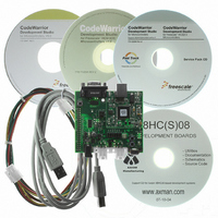
BOARD DEMO FOR 9S08 EL MCU
Manufacturer
Freescale Semiconductor
Type
MCUr
Datasheets
1.DEMO9S08EL32.pdf
(356 pages)
2.DEMO9S08EL32.pdf
(14 pages)
3.DEMO9S08EL32.pdf
(2 pages)
Specifications of DEMO9S08EL32
Contents
Evaluation Board
Processor To Be Evaluated
MC9S08EL32
Data Bus Width
8 bit
Interface Type
RS-232, USB
Operating Supply Voltage
12 V
Silicon Manufacturer
Freescale
Core Architecture
HCS08
Core Sub-architecture
HCS08
Silicon Core Number
MC9S08
Silicon Family Name
S08EL
Rohs Compliant
Yes
For Use With/related Products
MC9S08EL32
Lead Free Status / RoHS Status
Lead free / RoHS Compliant


After a repeated start condition (Sr), all other slave devices also compare the first seven bits of the first
byte of the slave address with their own addresses and test the eighth (R/W) bit. However, none of them
are addressed because R/W = 1 (for 10-bit devices) or the 11110XX slave address (for 7-bit devices) does
not match.
After the master-receiver has sent the first byte of the 10-bit address, the slave-transmitter sees an IIC
interrupt. Software must ensure the contents of IICD are ignored and not treated as valid data for this
interrupt.
11.4.3
General calls can be requested in 7-bit address or 10-bit address. If the GCAEN bit is set, the IIC matches
the general call address as well as its own slave address. When the IIC responds to a general call, it acts as
a slave-receiver and the IAAS bit is set after the address cycle. Software must read the IICD register after
the first byte transfer to determine whether the address matches is its own slave address or a general call.
If the value is 00, the match is a general call. If the GCAEN bit is clear, the IIC ignores any data supplied
from a general call address by not issuing an acknowledgement.
11.5
The IIC is disabled after reset. The IIC cannot cause an MCU reset.
11.6
The IIC generates a single interrupt.
An interrupt from the IIC is generated when any of the events in
is set. The interrupt is driven by bit IICIF (of the IIC status register) and masked with bit IICIE (of the IIC
control register). The IICIF bit must be cleared by software by writing a 1 to it in the interrupt routine. You
can determine the interrupt type by reading the status register.
11.6.1
The TCF (transfer complete flag) bit is set at the falling edge of the ninth clock to indicate the completion
of byte transfer.
Freescale Semiconductor
S
11110 + AD10 + AD9
Slave Address
1st 7 bits
Resets
Interrupts
General Call Address
Byte Transfer Interrupt
Table 11-11. Master-Receiver Addresses a Slave-Transmitter with a 10-bit Address
Match of received calling address
R/W
0
MC9S08EL32 Series and MC9S08SL16 Series Data Sheet, Rev. 3
Complete 1-byte transfer
A1
Interrupt Source
Arbitration Lost
Slave Address
2nd byte
AD[8:1]
Table 11-12. Interrupt Summary
A2
Sr
11110 + AD10 + AD9
Slave Address
Status
ARBL
IAAS
TCF
1st 7 bits
Table 11-12
IICIF
IICIF
IICIF
Flag
R/W
1
Local Enable
A3
occur, provided the IICIE bit
Inter-Integrated Circuit (S08IICV2)
IICIE
IICIE
IICIE
Data
A
...
Data
A
179
P
Related parts for DEMO9S08EL32
Image
Part Number
Description
Manufacturer
Datasheet
Request
R

Part Number:
Description:
Manufacturer:
Freescale Semiconductor, Inc
Datasheet:
Part Number:
Description:
Manufacturer:
Freescale Semiconductor, Inc
Datasheet:
Part Number:
Description:
Manufacturer:
Freescale Semiconductor, Inc
Datasheet:
Part Number:
Description:
Manufacturer:
Freescale Semiconductor, Inc
Datasheet:
Part Number:
Description:
Manufacturer:
Freescale Semiconductor, Inc
Datasheet:
Part Number:
Description:
Manufacturer:
Freescale Semiconductor, Inc
Datasheet:
Part Number:
Description:
Manufacturer:
Freescale Semiconductor, Inc
Datasheet:
Part Number:
Description:
Manufacturer:
Freescale Semiconductor, Inc
Datasheet:
Part Number:
Description:
Manufacturer:
Freescale Semiconductor, Inc
Datasheet:
Part Number:
Description:
Manufacturer:
Freescale Semiconductor, Inc
Datasheet:
Part Number:
Description:
Manufacturer:
Freescale Semiconductor, Inc
Datasheet:
Part Number:
Description:
Manufacturer:
Freescale Semiconductor, Inc
Datasheet:
Part Number:
Description:
Manufacturer:
Freescale Semiconductor, Inc
Datasheet:
Part Number:
Description:
Manufacturer:
Freescale Semiconductor, Inc
Datasheet:
Part Number:
Description:
Manufacturer:
Freescale Semiconductor, Inc
Datasheet: