DEMO9S08EL32 Freescale Semiconductor, DEMO9S08EL32 Datasheet - Page 224
DEMO9S08EL32
Manufacturer Part Number
DEMO9S08EL32
Description
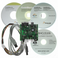
BOARD DEMO FOR 9S08 EL MCU
Manufacturer
Freescale Semiconductor
Type
MCUr
Datasheets
1.DEMO9S08EL32.pdf
(356 pages)
2.DEMO9S08EL32.pdf
(14 pages)
3.DEMO9S08EL32.pdf
(2 pages)
Specifications of DEMO9S08EL32
Contents
Evaluation Board
Processor To Be Evaluated
MC9S08EL32
Data Bus Width
8 bit
Interface Type
RS-232, USB
Operating Supply Voltage
12 V
Silicon Manufacturer
Freescale
Core Architecture
HCS08
Core Sub-architecture
HCS08
Silicon Core Number
MC9S08
Silicon Family Name
S08EL
Rohs Compliant
Yes
For Use With/related Products
MC9S08EL32
Lead Free Status / RoHS Status
Lead free / RoHS Compliant


This resolution affects the sampling accuracy of the SLIC module on receiving bytes, but only as far as
locating the sample point of each bit within a given byte. The best sample point of the bit may be off by as
much as one SLIC clock period from the exact center of the bit, if the proper SLCBT value for the desired
bit rate is an odd number of SLIC clock periods.
Figure 12-21
value of 30 SLIC clocks for the length of one bit time, and a filter prescaler of 1. This makes little
difference in the receive sampling of this particular bit, as the sample point is still within the bit and the
digital filter will catch any noise pulses shorter than 16 filter clocks long.The ideal value of SLCBT would
be 35 SLIC clocks, but the closest available value is 34, placing the sample point at 17 SLIC clocks into
the bit.
The error in the bit time value chosen by the user in the above example will grow throughout the byte, as
the sample point for the next bit will be only 30 SLIC clock cycles later (1 full bit time at this bit rate
setting). The SLIC resynchronizes upon every falling edge received. In a 0x00 data byte, however, there
are no falling edges after the beginning of the start bit. This means that the accumulated error of the
sampling point over the data byte with these settings could be as high as 30 SLIC clock cycles (10 bits x
{2 SLIC clocks due to user error + 1 SLIC clock resolution error}) placing it at the boundary between the
last bit and the stop bit. This could result in missampling and missing a byte framing error on the last bit
on high speed communications when the SLCBT count is relatively low. A properly chosen SLCBT value
would result in a maximum error of 10 SLIC clock counts over a given byte. This is less than one filter
delay time, and will not cause missampling of any of the bits in that byte. At the falling edge of the next
start bit, the SLIC will resynchronize and any accumulated sampling error returns to 0. The sampling error
becomes even less significant at lower speeds, when higher values of SLCBT are used to define a bit time,
as the worst case bit time resolution error is still only one SLIC clock per bit (or maximum of 10 SLIC
clocks per byte).
226
Desired Bit Rate:
External Crystal Frequency:
Therefore, the closest SLCBT value would be 416 SLIC clocks (SLCBT = 0x01A0).
8,000,000 Clock Out Periods
1 Second
shows an example of this error. In this example, the user has additionally chosen an incorrect
104.004 μs
1 Bit
MC9S08EL32 Series and MC9S08SL16 Series Data Sheet, Rev. 3
Figure 12-20. SLCBT Value Calculation Example 4
9,615 bps
8.000 MHz
X
X
1 SLIC Clock Period
1 SLIC Clock Period
2 Clock Out Period
250 ns
9,615 Bits
1 Second
=
=
=
1 SLIC Clock Period
416.017 SLIC Clock Periods
104.004 μs
1 Bit
250 ns
1 Bit
Freescale Semiconductor
Related parts for DEMO9S08EL32
Image
Part Number
Description
Manufacturer
Datasheet
Request
R

Part Number:
Description:
Manufacturer:
Freescale Semiconductor, Inc
Datasheet:
Part Number:
Description:
Manufacturer:
Freescale Semiconductor, Inc
Datasheet:
Part Number:
Description:
Manufacturer:
Freescale Semiconductor, Inc
Datasheet:
Part Number:
Description:
Manufacturer:
Freescale Semiconductor, Inc
Datasheet:
Part Number:
Description:
Manufacturer:
Freescale Semiconductor, Inc
Datasheet:
Part Number:
Description:
Manufacturer:
Freescale Semiconductor, Inc
Datasheet:
Part Number:
Description:
Manufacturer:
Freescale Semiconductor, Inc
Datasheet:
Part Number:
Description:
Manufacturer:
Freescale Semiconductor, Inc
Datasheet:
Part Number:
Description:
Manufacturer:
Freescale Semiconductor, Inc
Datasheet:
Part Number:
Description:
Manufacturer:
Freescale Semiconductor, Inc
Datasheet:
Part Number:
Description:
Manufacturer:
Freescale Semiconductor, Inc
Datasheet:
Part Number:
Description:
Manufacturer:
Freescale Semiconductor, Inc
Datasheet:
Part Number:
Description:
Manufacturer:
Freescale Semiconductor, Inc
Datasheet:
Part Number:
Description:
Manufacturer:
Freescale Semiconductor, Inc
Datasheet:
Part Number:
Description:
Manufacturer:
Freescale Semiconductor, Inc
Datasheet: