DEMO9S08EL32 Freescale Semiconductor, DEMO9S08EL32 Datasheet - Page 228
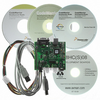
DEMO9S08EL32
Manufacturer Part Number
DEMO9S08EL32
Description
BOARD DEMO FOR 9S08 EL MCU
Manufacturer
Freescale Semiconductor
Type
MCUr
Datasheets
1.DEMO9S08EL32.pdf
(356 pages)
2.DEMO9S08EL32.pdf
(14 pages)
3.DEMO9S08EL32.pdf
(2 pages)
Specifications of DEMO9S08EL32
Contents
Evaluation Board
Processor To Be Evaluated
MC9S08EL32
Data Bus Width
8 bit
Interface Type
RS-232, USB
Operating Supply Voltage
12 V
Silicon Manufacturer
Freescale
Core Architecture
HCS08
Core Sub-architecture
HCS08
Silicon Core Number
MC9S08
Silicon Family Name
S08EL
Rohs Compliant
Yes
For Use With/related Products
MC9S08EL32
Lead Free Status / RoHS Status
Lead free / RoHS Compliant


12.6.18 Digital Receive Filter
The receiver section of the SLIC module includes a digital low-pass filter to remove narrow noise pulses
from the incoming message. A block diagram of the digital filter is shown in
12.6.18.1 Digital Filter Operation
The clock for the digital filter is provided by the SLIC Interface clock. At each positive edge of the clock
signal, the current state of the receiver input signal from the SLCRX pad is sampled. The SLCRX signal
state is used to determine whether the counter should increment or decrement at the next positive edge of
the clock signal.
The counter will increment if the input data sample is high but decrement if the input sample is low. The
counter will thus progress up towards the highest count value (determined by RXFP bit settings), on
average, the SLCRX signal remains high or progress down towards ‘0’ if, on average, the SLCRX signal
remains low. The final counter value which determines when the filter will change state is generated by
shifting the RXFP value right three positions and bitwise OR-ing the result with the value 0x0F. For
example, a prescale setting of divide by 3 would give a count value of 0x2F.
When the counter eventually reaches this value, the digital filter decides that the condition of the SLCRX
signal is at a stable logic level 1 and the data latch is set, causing the filtered Rx data signal to become a
logic level 1. Furthermore, the counter is prevented from overflowing and can only be decremented from
this state.
Alternatively, when the counter eventually reaches the value ‘0’, the digital filter decides that the condition
of the SLCRX signal is at a stable logic level 0 and the data latch is reset, causing the filtered Rx data signal
to become a logic level 0. Furthermore, the counter is prevented from underflowing and can only be
incremented from this state.
The data latch will retain its value until the counter next reaches the opposite end point, signifying a
definite transition of the SLCRX signal.
230
SLCRX PIN
RX DATA
FROM
D
INPUT
SYNC
Q
Figure 12-22. SLIC Module Rx Digital Filter Block Diagram
MC9S08EL32 Series and MC9S08SL16 Series Data Sheet, Rev. 3
HOLD
UP/DOWN
4-BIT UP/DOWN COUNTER
OUT
4
PRESCALER (RXFP)
DIGITAL RX FILTER
COMPARATOR
EDGE &
COUNT
Figure
D
Freescale Semiconductor
12-22.
Q
SLIC CLOCK
FILTERED
RX DATA OUT
Related parts for DEMO9S08EL32
Image
Part Number
Description
Manufacturer
Datasheet
Request
R

Part Number:
Description:
Manufacturer:
Freescale Semiconductor, Inc
Datasheet:
Part Number:
Description:
Manufacturer:
Freescale Semiconductor, Inc
Datasheet:
Part Number:
Description:
Manufacturer:
Freescale Semiconductor, Inc
Datasheet:
Part Number:
Description:
Manufacturer:
Freescale Semiconductor, Inc
Datasheet:
Part Number:
Description:
Manufacturer:
Freescale Semiconductor, Inc
Datasheet:
Part Number:
Description:
Manufacturer:
Freescale Semiconductor, Inc
Datasheet:
Part Number:
Description:
Manufacturer:
Freescale Semiconductor, Inc
Datasheet:
Part Number:
Description:
Manufacturer:
Freescale Semiconductor, Inc
Datasheet:
Part Number:
Description:
Manufacturer:
Freescale Semiconductor, Inc
Datasheet:
Part Number:
Description:
Manufacturer:
Freescale Semiconductor, Inc
Datasheet:
Part Number:
Description:
Manufacturer:
Freescale Semiconductor, Inc
Datasheet:
Part Number:
Description:
Manufacturer:
Freescale Semiconductor, Inc
Datasheet:
Part Number:
Description:
Manufacturer:
Freescale Semiconductor, Inc
Datasheet:
Part Number:
Description:
Manufacturer:
Freescale Semiconductor, Inc
Datasheet:
Part Number:
Description:
Manufacturer:
Freescale Semiconductor, Inc
Datasheet: