DEMO9S08EL32 Freescale Semiconductor, DEMO9S08EL32 Datasheet - Page 300
DEMO9S08EL32
Manufacturer Part Number
DEMO9S08EL32
Description
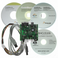
BOARD DEMO FOR 9S08 EL MCU
Manufacturer
Freescale Semiconductor
Type
MCUr
Datasheets
1.DEMO9S08EL32.pdf
(356 pages)
2.DEMO9S08EL32.pdf
(14 pages)
3.DEMO9S08EL32.pdf
(2 pages)
Specifications of DEMO9S08EL32
Contents
Evaluation Board
Processor To Be Evaluated
MC9S08EL32
Data Bus Width
8 bit
Interface Type
RS-232, USB
Operating Supply Voltage
12 V
Silicon Manufacturer
Freescale
Core Architecture
HCS08
Core Sub-architecture
HCS08
Silicon Core Number
MC9S08
Silicon Family Name
S08EL
Rohs Compliant
Yes
For Use With/related Products
MC9S08EL32
Lead Free Status / RoHS Status
Lead free / RoHS Compliant


Timer/PWM Module (S08TPMV3)
16.6.2.1.2
When CPWMS=1, TOF gets set when the timer counter changes direction from up-counting to
down-counting at the end of the terminal count (the value in the modulo register). In this case the TOF
corresponds to the end of a PWM period.
16.6.2.2
The meaning of channel interrupts depends on the channel’s current mode (input-capture, output-compare,
edge-aligned PWM, or center-aligned PWM).
16.6.2.2.1
When a channel is configured as an input capture channel, the ELSnB:ELSnA control bits select no edge
(off), rising edges, falling edges or any edge as the edge which triggers an input capture event. When the
selected edge is detected, the interrupt flag is set. The flag is cleared by the two-step sequence described
in
16.6.2.2.2
When a channel is configured as an output compare channel, the interrupt flag is set each time the main
timer counter matches the 16-bit value in the channel value register. The flag is cleared by the two-step
sequence described
16.6.2.2.3
For channels configured for PWM operation there are two possibilities. When the channel is configured
for edge-aligned PWM, the channel flag gets set when the timer counter matches the channel value register
which marks the end of the active duty cycle period. When the channel is configured for center-aligned
PWM, the timer count matches the channel value register twice during each PWM cycle. In this CPWM
case, the channel flag is set at the start and at the end of the active duty cycle period which are the times
when the timer counter matches the channel value register. The flag is cleared by the two-step sequence
described
16.7
302
Section 16.6.2, “Description of Interrupt Operation.”
1. Write to TPMxCNTH:L registers
2. Read of TPMxCNTH:L registers
(TPMxCNTH:TPMxCNTL)) [SE110-TPM case 7]
Any write to TPMxCNTH or TPMxCNTL registers in TPM v3 clears the TPM counter
(TPMxCNTH:L) and the prescaler counter. Instead, in the TPM v2 only the TPM counter is cleared
in this case.
(TPMxCNTH:TPMxCNTL))
— In TPM v3, any read of TPMxCNTH:L registers during BDM mode returns the value of the
The Differences from TPM v2 to TPM v3
Section 16.6.2, “Description of Interrupt Operation.”
TPM counter that is frozen. In TPM v2, if only one byte of the TPMxCNTH:L registers was
read before the BDM mode became active, then any read of TPMxCNTH:L registers during
Channel Event Interrupt Description
Center-Aligned PWM Case
Input Capture Events
Output Compare Events
PWM End-of-Duty-Cycle Events
Section 16.6.2, “Description of Interrupt Operation.”
MC9S08EL32 Series and MC9S08SL16 Series Data Sheet, Rev. 3
(Section 16.3.2, “TPM-Counter Registers
(Section 16.3.2, “TPM-Counter Registers
Freescale Semiconductor
Related parts for DEMO9S08EL32
Image
Part Number
Description
Manufacturer
Datasheet
Request
R

Part Number:
Description:
Manufacturer:
Freescale Semiconductor, Inc
Datasheet:
Part Number:
Description:
Manufacturer:
Freescale Semiconductor, Inc
Datasheet:
Part Number:
Description:
Manufacturer:
Freescale Semiconductor, Inc
Datasheet:
Part Number:
Description:
Manufacturer:
Freescale Semiconductor, Inc
Datasheet:
Part Number:
Description:
Manufacturer:
Freescale Semiconductor, Inc
Datasheet:
Part Number:
Description:
Manufacturer:
Freescale Semiconductor, Inc
Datasheet:
Part Number:
Description:
Manufacturer:
Freescale Semiconductor, Inc
Datasheet:
Part Number:
Description:
Manufacturer:
Freescale Semiconductor, Inc
Datasheet:
Part Number:
Description:
Manufacturer:
Freescale Semiconductor, Inc
Datasheet:
Part Number:
Description:
Manufacturer:
Freescale Semiconductor, Inc
Datasheet:
Part Number:
Description:
Manufacturer:
Freescale Semiconductor, Inc
Datasheet:
Part Number:
Description:
Manufacturer:
Freescale Semiconductor, Inc
Datasheet:
Part Number:
Description:
Manufacturer:
Freescale Semiconductor, Inc
Datasheet:
Part Number:
Description:
Manufacturer:
Freescale Semiconductor, Inc
Datasheet:
Part Number:
Description:
Manufacturer:
Freescale Semiconductor, Inc
Datasheet: