MCP6V01DM-VOS Microchip Technology, MCP6V01DM-VOS Datasheet - Page 30
MCP6V01DM-VOS
Manufacturer Part Number
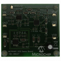
MCP6V01DM-VOS
Description
DEMO BOARD FOR MCP6V01
Manufacturer
Microchip Technology
Specifications of MCP6V01DM-VOS
Channels Per Ic
1 - Single
Amplifier Type
Chopper (Zero-Drift)
Output Type
Rail-to-Rail
Slew Rate
0.5 V/µs
Current - Output / Channel
22mA
Operating Temperature
-40°C ~ 125°C
Voltage - Supply, Single/dual (±)
1.8 V ~ 5.5 V
Board Type
Fully Populated
Utilized Ic / Part
MCP6V01
Silicon Manufacturer
Microchip
Application Sub Type
Operational Amplifier
Kit Application Type
Amplifier
Silicon Core Number
MCP6V01, MCP6V03, MCP6V06, MCP6V08
Kit Contents
Board
Lead Free Status / RoHS Status
Lead free / RoHS Compliant
-3db Bandwidth
-
Current - Supply (main Ic)
-
Lead Free Status / Rohs Status
Lead free / RoHS Compliant


MCP6V01/2/3
4.4.3
Figure 4-18
and temperature sensor used in a thermocouple
application. The type K thermocouple senses the
temperature at the hot junction (T
voltage at V
gain is is set so that V
the output of a temperature sensor, which produces a
voltage proportional to the temperature (in °C) at the
cold junction (T
that V
EQUATION 4-5:
FIGURE 4-18:
Simplified Circuit.
Figure 4-19
this circuit. The dashed red arrow indicates a thermally
conductive connection between the thermocouple and
the MCP9700A; it needs to be very short and have low
thermal resistance.
FIGURE 4-19:
DS22058C-page 30
(hot junction
R
at T
V
V
V
V
TH
≈ (10 mV/°C) (T
MCP9700A
1
2
3
4
(cold junction
MCP1541
Type K
≈ T
= (1.00V)
= T
= 250V
HJ
4
= Thevenin Equivalent Resistance (e.g.: 10 kΩ)
40 µV/°C
Type K
Thermocouple
V
V
is 0.50V when T
)
HJ
CJ
DD
DD
(40 µV/°C)
at T
(10 mV/°C) + (0.50V)
1
THERMOCOUPLE SENSOR
shows a more complete implementation of
shows a simplified diagram of an amplifier
1
V
proportional to T
+ (V
CJ
1
R
CJ
TH
)
4.100(R
), and with a 0.50V offset. V
(R
(R
2
HJ
= Thevenin Equivalent Resistance
– V
(R
TH
TH
4
– T
V
V
V
TH
)/250
)/250
/T
Thermocouple Sensor;
Thermocouple Sensor.
3
2
1
3
HJ
)
(R
(R
)
HJ
CJ
TH
– T
TH
TH
) + (0.50V)
is 10 mV/°C. V
)
(R
(R
)/250
)/250
HJ
0.5696(R
CJ
(R
TH
TH
C
C
(in °C). The amplifier’s
is 0°C.
TH
)
)
HJ
MCP6V01
)
), and produces a
(R
(R
TH
C
C
TH
TH
3 kΩ
)
3
MCP6V01
)
)
represents
2
is set so
V
V
4
4
The MCP9700A senses the temperature at its physical
location. It needs to be at the same temperature as the
cold junction (T
The MCP1541 produces a 4.10V output, assuming
V
4.100(R
nin
1.3224(R
top right R
0.5696(R
V
thermocouple’s non-linearity. The ADC can use the
MCP1541 as its voltage reference. Alternately, an
absolute reference inside a PICmicro
instead of the MCP1541.
4.4.4
Figure 4-20
offset voltage of another op amp. R
the offset error seen at the other op amp’s input; the
integration needs to be slow enough to be stable (with
the feedback provided by R
FIGURE 4-20:
4.4.5
Use high gain before a comparator to improve the
latter’s performance. Do not use MCP6V01/2/3 as a
comparator by itself; the V
not operate properly without a feedback loop.
FIGURE 4-21:
DD
4
should be converted to digital, then corrected for the
V
V
V
V
DD
is at 5.0V. This voltage, tied to a resistor ladder of
IN
IN
DD
equivalent
/2
/2
TH
TH
TH
) and 1.3224(R
R
R
TH
R
) resistor is combined in parallel with the
) resistor.
OFFSET VOLTAGE CORRECTION
PRECISION COMPARATOR
2
shows a MCP6V01 correcting the input
1
R
1
R
resistor (in
2
MCP6V01
2
CJ
), and produces V
of
R
3
C
2
MCP6V01
Offset Correction.
Precision Comparator.
1.00V
© 2008 Microchip Technology Inc.
MCP6541
TH
R
Figure
OS
1
4
), would produce a Theve-
3 kΩ
and R
R
correction circuitry does
5
and
4-18), producing the
3
3
2
).
R
1 kΩ
(Figure
and C
250(R
3
®
MCP6XXX
can be used
2
TH
4-16).
V
integrate
V
).
OUT
OUT
The
Related parts for MCP6V01DM-VOS
Image
Part Number
Description
Manufacturer
Datasheet
Request
R

Part Number:
Description:
IC OPAMP AUTO-ZERO SNGL 8SOIC
Manufacturer:
Microchip Technology
Datasheet:

Part Number:
Description:
300 ?A, Auto-Zeroed Op Amps
Manufacturer:
MICROCHIP [Microchip Technology]
Datasheet:
Part Number:
Description:
Op Amps Sngl Auto-Zero Op Amp E temp
Manufacturer:
Microchip Technology

Part Number:
Description:
300 ?a, Auto-zeroed Op Amps
Manufacturer:
Microchip Technology Inc.
Datasheet:
Part Number:
Description:
Manufacturer:
Microchip Technology Inc.
Datasheet:
Part Number:
Description:
Manufacturer:
Microchip Technology Inc.
Datasheet:
Part Number:
Description:
Manufacturer:
Microchip Technology Inc.
Datasheet:
Part Number:
Description:
Manufacturer:
Microchip Technology Inc.
Datasheet:
Part Number:
Description:
Manufacturer:
Microchip Technology Inc.
Datasheet:
Part Number:
Description:
Manufacturer:
Microchip Technology Inc.
Datasheet:
Part Number:
Description:
Manufacturer:
Microchip Technology Inc.
Datasheet: