STEVAL-IFW001V1 STMicroelectronics, STEVAL-IFW001V1 Datasheet - Page 25
STEVAL-IFW001V1
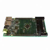
Manufacturer Part Number
STEVAL-IFW001V1
Description
BOARD EVAL BASED ON STR912FA
Manufacturer
STMicroelectronics
Datasheets
1.STEVAL-IFW001V1.pdf
(102 pages)
2.STEVAL-IFW001V1.pdf
(9 pages)
3.STEVAL-IFW001V1.pdf
(7 pages)
Specifications of STEVAL-IFW001V1
Design Resources
STEVAL-IFW001V1 Gerber Files STEVAL-IFW001V1 Schematic STEVAL-IFW001V1 Bill of Material
Main Purpose
Interface, Ethernet
Embedded
Yes, MCU, 32-Bit
Utilized Ic / Part
E-STE101P, STR912FAW44
Primary Attributes
Dual Ethernet Transceivers for Full Duplex Communication
Secondary Attributes
Up to 32 MII Addresses, UART, I2C, SPI, with RJ45 Connectors
Silicon Manufacturer
ST Micro
Core Architecture
ARM
Core Sub-architecture
ARM9
Silicon Core Number
STR9
Silicon Family Name
STR91x
For Use With
497-8263 - BOARD EXTENSION STEVAL-IFW001V1
Lead Free Status / RoHS Status
Lead free / RoHS Compliant
Other names
497-8262


STR91xFAxxx
3.12.2
3.13
Note:
3.13.1
Battery supply
An optional stand-by voltage from a battery or other source may be connected to pin VBATT
to retain the contents of SRAM in the event of a loss of the main digital supplies (V
V
VBATT pin when the voltage of V
battery supply, the LVD must be enabled.
The VBATT pin also supplies power to the RTC unit, allowing the RTC to function even when
the main digital supplies (V
it is possible to select whether or not to power from VBATT only the RTC unit, or power the
RTC unit and the SRAM when the STR91xFA device is powered off.
System supervisor
The STR91xFA monitors several system and environmental inputs and will generate a
global reset, a system reset, or an interrupt based on the nature of the input and
configurable settings. A global reset clears all functions on the STR91xFA, a system reset
will clear all but the Clock Control Unit (CCU) settings and the system status register. At any
time, firmware may reset individual on-chip peripherals. System supervisor inputs include:
●
●
●
●
●
●
GR: means the input causes Global Reset, SR: means the input causes System Reset
The CPU may read a status register after a reset event to determine if the reset was caused
by a watchdog timer timeout or a voltage supply drop out. This status register is cleared only
by a power up reset.
Supply voltage brownout
Each operating voltage source (V
Detect (LVD) circuitry. The LVD will generate an early warning interrupt to the CPU when
voltage sags on either V
applications because the system can perform an orderly shutdown before the batteries
become too weak. The voltage trip point to cause a brown out interrupt is typically 0.25V
above the LVD dropout thresholds that cause a reset.
CPU firmware may prevent all brown-out interrupts by writing to interrupt mask registers at
run-time.
DDQ)
GR: CPU voltage supply (V
GR: I/O voltage supply (V
GR: Power-Up condition
SR: Watchdog timer timeout
SR: External reset pin (RESET_INn)
SR: JTAG debug reset command
. The SRAM will automatically switch its supply from the internal V
DD
DD
or V
Doc ID 13495 Rev 6
and V
DDQ
DDQ
DD
DD
DD
) drop out or brown out
) drop out or brown out
voltage inputs. This is an advantage for battery powered
drops below the LVD threshold. In order to use the
DDQ
and V
) are switched off. By configuring the RTC register,
DDQ
) is monitored separately by the Low Voltage
Functional overview
DD
source to the
DD
25/102
and
Related parts for STEVAL-IFW001V1
Image
Part Number
Description
Manufacturer
Datasheet
Request
R

Part Number:
Description:
BOARD EVAL SPZB260 MOD FOR STR9
Manufacturer:
STMicroelectronics
Datasheet:

Part Number:
Description:
BOARD EVAL EXTENSION SN250
Manufacturer:
STMicroelectronics
Datasheet:

Part Number:
Description:
BOARD EVAL AB-54003L-512
Manufacturer:
STMicroelectronics
Datasheet:

Part Number:
Description:
BOARD REF DESIGN RF DMOS PWR AMP
Manufacturer:
STMicroelectronics
Datasheet:

Part Number:
Description:
BOARD EVAL PWR AMP AB-84008L-470
Manufacturer:
STMicroelectronics
Datasheet:

Part Number:
Description:
BOARD EVAL FOR STM32F103XX
Manufacturer:
STMicroelectronics
Datasheet:

Part Number:
Description:
BOARD EVAL AB-54003L-512
Manufacturer:
STMicroelectronics
Datasheet:

Part Number:
Description:
BOARD SMART PLUG STM32 SPZB260PR
Manufacturer:
STMicroelectronics
Datasheet:

Part Number:
Description:
BOARD DEMO BLUETOOTH SPBT2532C2
Manufacturer:
STMicroelectronics
Datasheet:
Part Number:
Description:
ZIGBEE USB DONGLE EVAL KIT
Manufacturer:
STMicroelectronics
Datasheet:
Part Number:
Description:
STMicroelectronics [RIPPLE-CARRY BINARY COUNTER/DIVIDERS]
Manufacturer:
STMicroelectronics
Datasheet:
Part Number:
Description:
STMicroelectronics [LIQUID-CRYSTAL DISPLAY DRIVERS]
Manufacturer:
STMicroelectronics
Datasheet:

Part Number:
Description:
BOARD EVAL FOR MEMS SENSORS
Manufacturer:
STMicroelectronics
Datasheet: