STEVAL-IFW001V1 STMicroelectronics, STEVAL-IFW001V1 Datasheet - Page 24
STEVAL-IFW001V1
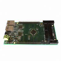
Manufacturer Part Number
STEVAL-IFW001V1
Description
BOARD EVAL BASED ON STR912FA
Manufacturer
STMicroelectronics
Datasheets
1.STEVAL-IFW001V1.pdf
(102 pages)
2.STEVAL-IFW001V1.pdf
(9 pages)
3.STEVAL-IFW001V1.pdf
(7 pages)
Specifications of STEVAL-IFW001V1
Design Resources
STEVAL-IFW001V1 Gerber Files STEVAL-IFW001V1 Schematic STEVAL-IFW001V1 Bill of Material
Main Purpose
Interface, Ethernet
Embedded
Yes, MCU, 32-Bit
Utilized Ic / Part
E-STE101P, STR912FAW44
Primary Attributes
Dual Ethernet Transceivers for Full Duplex Communication
Secondary Attributes
Up to 32 MII Addresses, UART, I2C, SPI, with RJ45 Connectors
Silicon Manufacturer
ST Micro
Core Architecture
ARM
Core Sub-architecture
ARM9
Silicon Core Number
STR9
Silicon Family Name
STR91x
For Use With
497-8263 - BOARD EXTENSION STEVAL-IFW001V1
Lead Free Status / RoHS Status
Lead free / RoHS Compliant
Other names
497-8262


Functional overview
3.11.2
Note:
3.11.3
3.12
3.12.1
24/102
Idle mode
In this mode the CPU suspends code execution and the CPU and FMI clocks are turned off
immediately after firmware sets the Idle Bit. Various peripherals continue to run based on
the settings of the mask registers that exist just prior to entering Idle Mode. There are 3
ways to exit Idle Mode and return to Run Mode:
●
●
●
It is possible to remain in Idle Mode for the majority of the time and the RTC can be
programmed to periodically wake up to perform a brief task or check status.
Sleep mode
In this mode all clock circuits except the RTC are turned off and main oscillator input pins
X1_CPU and X2_CPU are disabled. The RTC clock is required for the CPU to exit Sleep
Mode. The entire chip is quiescent (except for RTC and wake-up circuitry). There are three
means to exit Sleep Mode and re-start the system:
●
●
●
Voltage supplies
The STR91xFA requires two separate operating voltage supplies. The CPU and memories
operate from a 1.65V to 2.0V on the VDD pins, and the I/O ring operates at 2.7V to 3.6V on
the VDDQ pins.
In Standby mode, both VDD and VDDQ must be shut down. Otherwise the specified
maximum power consumption for Standby mode (I
exceeded. Leakage may occur if only one of the voltage supplies is off.
Independent A/D converter supply and reference voltage
The ADC unit on 128-pin and 144-ball packages has an isolated analog voltage supply input
at pin AVDD to accept a very clean voltage source, independent of the digital voltage
supplies. Additionally, an isolated analog supply ground connection is provided on pin AVSS
only on 128-pin and 144-ball packages for further ADC supply isolation. On 80-pin
packages, the analog voltage supply is shared with the ADC reference voltage pin (as
described next), and the analog ground is shared with the digital ground at a single point in
the STR91xFA device on pin AVSS_VSSQ.
A separate external analog reference voltage input for the ADC unit is available on 128-pin
and 144-ball packages at the AVREF pin for better accuracy on low voltage inputs. For 80-
pin packages, the ADC reference voltage is tied internally to the ADC unit supply voltage at
pin AVREF_AVDD, meaning the ADC reference voltage is fixed to the ADC unit supply
voltage.
See
AVDD, AVREF, and AVREF_AVDD.
Table 11: Operating
Any reset (external reset pin, watchdog, low-voltage, power-up, JTAG debug command)
Any interrupt (external, internal peripheral, RTC alarm or interval)
Input from wake-up unit on GPIO pins
Some resets (external reset pin, low-voltage, power-up, JTAG debug command)
RTC alarm
Input from wake-up unit
conditions, for restrictions to the relative voltage levels of VDDQ,
Doc ID 13495 Rev 6
RTC_STBY
and I
SRAM_STBY
STR91xFAxxx
) may be
Related parts for STEVAL-IFW001V1
Image
Part Number
Description
Manufacturer
Datasheet
Request
R

Part Number:
Description:
BOARD EVAL SPZB260 MOD FOR STR9
Manufacturer:
STMicroelectronics
Datasheet:

Part Number:
Description:
BOARD EVAL EXTENSION SN250
Manufacturer:
STMicroelectronics
Datasheet:

Part Number:
Description:
BOARD EVAL AB-54003L-512
Manufacturer:
STMicroelectronics
Datasheet:

Part Number:
Description:
BOARD REF DESIGN RF DMOS PWR AMP
Manufacturer:
STMicroelectronics
Datasheet:

Part Number:
Description:
BOARD EVAL PWR AMP AB-84008L-470
Manufacturer:
STMicroelectronics
Datasheet:

Part Number:
Description:
BOARD EVAL FOR STM32F103XX
Manufacturer:
STMicroelectronics
Datasheet:

Part Number:
Description:
BOARD EVAL AB-54003L-512
Manufacturer:
STMicroelectronics
Datasheet:

Part Number:
Description:
BOARD SMART PLUG STM32 SPZB260PR
Manufacturer:
STMicroelectronics
Datasheet:

Part Number:
Description:
BOARD DEMO BLUETOOTH SPBT2532C2
Manufacturer:
STMicroelectronics
Datasheet:
Part Number:
Description:
ZIGBEE USB DONGLE EVAL KIT
Manufacturer:
STMicroelectronics
Datasheet:
Part Number:
Description:
STMicroelectronics [RIPPLE-CARRY BINARY COUNTER/DIVIDERS]
Manufacturer:
STMicroelectronics
Datasheet:
Part Number:
Description:
STMicroelectronics [LIQUID-CRYSTAL DISPLAY DRIVERS]
Manufacturer:
STMicroelectronics
Datasheet:

Part Number:
Description:
BOARD EVAL FOR MEMS SENSORS
Manufacturer:
STMicroelectronics
Datasheet: