DLP-2232M-G DLP Design Inc, DLP-2232M-G Datasheet - Page 19
DLP-2232M-G
Manufacturer Part Number
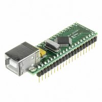
DLP-2232M-G
Description
MODULE USB ADAPTER FOR FT2232D
Manufacturer
DLP Design Inc
Datasheet
1.DLP-2232M-G.pdf
(33 pages)
Specifications of DLP-2232M-G
Main Purpose
Interface, USB 2.0 to UART (RS232) Bridge
Embedded
No
Utilized Ic / Part
FT2232D
Primary Attributes
Full Speed USB to High-Speed UART
Secondary Attributes
Royalty-Free Drivers, 2K EEPROM
Interface Type
USB
Data Bus Width
8 bit
Operating Supply Voltage
4.35 V to 5.25 V
Product
Interface Modules
For Use With/related Products
FT2232D
Lead Free Status / RoHS Status
Lead free / RoHS Compliant
Lead Free Status / RoHS Status
Lead free / RoHS Compliant, Lead free / RoHS Compliant
Other names
813-1000


9.2 245 FIFO Interface Mode Signal Descriptions and Configuration
When either Channel A or Channel B are in 245 FIFO mode, the IO signal lines are
configured as follows.
FIFO DATA BUS GROUP
Channel A
40
39
38
38
36
35
34
33
FIFO CONTROL INTERFACE GROUP
Channel A
32
31
30
29
28
*Note 10:
FT2232D. These can be programmed to gently pull low during USB suspend
(PWREN# = “1”) by setting this option in the EEPROM.
Rev 1.6 (May 2009)
Pin#
Pin#
In Input Mode, these pins are pulled to VCCIOx via 200K resistors in the
Channel B
13
12
11
10
9
8
7
6
Channel B
5
4
3
2
1
Signal
D0
D1
D2
D3
D4
D5
D6
D7
Signal
RXF#
TXE#
RD#
WR
SI/WUx
*Note 10
Type
I/O
I/O
I/O
I/O
I/O
I/O
I/O
I/O
Type
OUTPUT
OUTPUT
INPUT
INPUT
INPUT
Description
FIFO Data Bus Bit 0
FIFO Data Bus Bit 1
FIFO Data Bus Bit 2
FIFO Data Bus Bit 3
FIFO Data Bus Bit 4
FIFO Data Bus Bit 5
FIFO Data Bus Bit 6
FIFO Data Bus Bit 7
Description
When high, do not read data from the FIFO. When
low, there is data available in the FIFO which can be
read by strobing RD# low then high again
When high, do not write data into the FIFO. When
low, data can be written into the FIFO by transitioning
WR from high to low.
Enables Current FIFO Data Byte on D0..D7 when low.
Fetches the next FIFO Data Byte (if available) from
the Receive FIFO Buffer when RD# goes from low to
high
Writes the Data Byte on the D0..D7 into the Transmit
FIFO Buffer on the falling edge of WR.
functions on a single pin. If USB is in suspend mode
(PWREN# = 1) and remote wakeup is enabled in the
EEPROM, strobing this pin low will cause the device
to request a resume on the USB Bus. Normally, this
can be used to wake up the Host PC.
During normal operation (PWREN# = 0), if this pin is
strobed low any data in the device TX buffer will be
sent out over USB on the next Bulk-IN request from
the drivers regardless of the pending packet size. This
can be used to optimize USB transfer speed for some
applications. Tie this pin to VCCIOx if not used.
19
The Send Immediate / WakeUp signal combines two
. * Note 10
DLP-2232M-G DLP Design, Inc.
* Note 11
* Note 10
* Note 11
Related parts for DLP-2232M-G
Image
Part Number
Description
Manufacturer
Datasheet
Request
R

Part Number:
Description:
MODULE USB-TO-TTL PARL FIFO CONV
Manufacturer:
DLP Design Inc
Datasheet:

Part Number:
Description:
KIT DEV DLP LIGHTCOMANDER
Manufacturer:
Logic
Datasheet:

Part Number:
Description:
MODULE DATA-ACQUISITION 8-CH
Manufacturer:
DLP Design Inc
Datasheet:

Part Number:
Description:
MODULE DATA-ACQUISITION 20-CH
Manufacturer:
DLP Design Inc
Datasheet:

Part Number:
Description:
RFID READER/WRITER SNGL-CH OEM
Manufacturer:
DLP Design Inc
Datasheet:

Part Number:
Description:
Interface Modules & Development Tools DLP-245PL PACKAGED w/CCS Compiler
Manufacturer:
DLP Design Inc

Part Number:
Description:
Interface Modules & Development Tools DLP-245PB-G BOARD + CCS Compiler
Manufacturer:
DLP Design Inc
Datasheet:

Part Number:
Description:
Interface Modules & Development Tools DLP-TILT SENSOR ACCEL VIBRATION
Manufacturer:
DLP Design Inc

Part Number:
Description:
MODULE USB-MCU FT245RL W/16F877A
Manufacturer:
DLP Design Inc
Datasheet:

Part Number:
Description:
MODULE USB-TO-FPGA TRAINING TOOL
Manufacturer:
DLP Design Inc
Datasheet:

Part Number:
Description:
MODULE USB-MCU FT232R W/18F2410
Manufacturer:
DLP Design Inc
Datasheet:

Part Number:
Description:
MODULE USB-MCU FT245RL W/SX48
Manufacturer:
DLP Design Inc
Datasheet:

Part Number:
Description:
MODULE USB-MCU FT2232D W/16F877A
Manufacturer:
DLP Design Inc
Datasheet:

Part Number:
Description:
MODULE USB-TO-FPGA SPARTAN3
Manufacturer:
DLP Design Inc
Datasheet:

Part Number:
Description:
MOD USB-MCU FT245RL W/18LF8722
Manufacturer:
DLP Design Inc
Datasheet: