DLP-2232M-G DLP Design Inc, DLP-2232M-G Datasheet - Page 17
DLP-2232M-G
Manufacturer Part Number
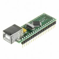
DLP-2232M-G
Description
MODULE USB ADAPTER FOR FT2232D
Manufacturer
DLP Design Inc
Datasheet
1.DLP-2232M-G.pdf
(33 pages)
Specifications of DLP-2232M-G
Main Purpose
Interface, USB 2.0 to UART (RS232) Bridge
Embedded
No
Utilized Ic / Part
FT2232D
Primary Attributes
Full Speed USB to High-Speed UART
Secondary Attributes
Royalty-Free Drivers, 2K EEPROM
Interface Type
USB
Data Bus Width
8 bit
Operating Supply Voltage
4.35 V to 5.25 V
Product
Interface Modules
For Use With/related Products
FT2232D
Lead Free Status / RoHS Status
Lead free / RoHS Compliant
Lead Free Status / RoHS Status
Lead free / RoHS Compliant, Lead free / RoHS Compliant
Other names
813-1000


Figure 10a shows how to configure the DLP-2232M-G to interface with a 5V
microcontroller. In this example, the USB port is the power source for VCCIOA and
VCCIOB, which in turn will cause the device interface IO pins on both channels to drive
out at the 5V level. In this configuration, the on-board MOSFET power switch controls
power to the microcontroller. Care must be taken to ensure all microcontroller circuitry,
when combined with the DLP-2232M-G circuitry, does not exceed the maximum
available current from the USB port of 500mA for a high-powered USB device.
8.2.2 USB Self-Powered, 5V Systems
Figure 10b is an example of a DLP-2232M-G USB self-powered design with 5V
interface. In this case, the VCCIOA and VCCIOB pins are supplied by an external 5V
supply in order to make both of the device’s IO channels drive out at 5V logic level, thus
allowing them to be connected to a 5V microcontroller or other external logic.
A USB self-powered design uses its own power supplies, and does not draw any of its
power from the USB bus. In such cases, no special care need be taken to meet the USB
suspend current (0.5 mA) as the device does not get it’s power from the USB port.
Note that if the SI/WUx pins are not being used they should be pulled up to the same
supply as their respective VCCIOx pin.
8.2.3 USB Bus-Powered, 3.3V Systems
Figure 10c shows how to configure the DLP-2232M-G to interface with a 3.3V
microcontroller. In this example, a discrete 3.3V regulator is used to supply the 3.3V
logic from the USB supply. VCCIOA and VCCIOB are connected to the output of the
3.3V regulator, which in turn will cause the device interface IO pins on both channels to
drive out at 3.3V level. It is also possible to have one IO interface channel driving out at
5V level, and the other at 3.3V level. In this case one of the VCCIOx pins would be
connected to 5V, and the other connected to 3.3V. For USB bus powered circuits, care
must be taken when selecting the regulator. The regulator must be capable of sustaining
its output voltage with an input voltage of 4.35 volts. A Low Drop Out (LDO) regulator
must be selected. An example of a regulator family that meets these requirements is the
MicroChip (Telcom) TC55 Series. These devices can supply up to 250mA current.
Note: It should be emphasized that the 3.3V supply, for VCCIOx in a bus powered design
with a 3.3V logic interface, should come from an LDO that is supplied by the USB bus,
not from any other source. Please also note that if the SI/WUx pins are not being used
they should be pulled up to the same supply as their respective VCCIOx pin.
8.2.4 USB Self-Powered, 3.3V Systems
Figure 10d is an example of a DLP-2232M-G USB self-powered design with 3.3V
interface. In this case, the VCCIOA and VCCIOB pins are supplied by an external 3.3V
supply in order to make both of the device’s IO channels drive out at 3.3V logic level,
Rev 1.6 (May 2009)
17
DLP-2232M-G DLP Design, Inc.
Related parts for DLP-2232M-G
Image
Part Number
Description
Manufacturer
Datasheet
Request
R

Part Number:
Description:
MODULE USB-TO-TTL PARL FIFO CONV
Manufacturer:
DLP Design Inc
Datasheet:

Part Number:
Description:
KIT DEV DLP LIGHTCOMANDER
Manufacturer:
Logic
Datasheet:

Part Number:
Description:
MODULE DATA-ACQUISITION 8-CH
Manufacturer:
DLP Design Inc
Datasheet:

Part Number:
Description:
MODULE DATA-ACQUISITION 20-CH
Manufacturer:
DLP Design Inc
Datasheet:

Part Number:
Description:
RFID READER/WRITER SNGL-CH OEM
Manufacturer:
DLP Design Inc
Datasheet:

Part Number:
Description:
Interface Modules & Development Tools DLP-245PL PACKAGED w/CCS Compiler
Manufacturer:
DLP Design Inc

Part Number:
Description:
Interface Modules & Development Tools DLP-245PB-G BOARD + CCS Compiler
Manufacturer:
DLP Design Inc
Datasheet:

Part Number:
Description:
Interface Modules & Development Tools DLP-TILT SENSOR ACCEL VIBRATION
Manufacturer:
DLP Design Inc

Part Number:
Description:
MODULE USB-MCU FT245RL W/16F877A
Manufacturer:
DLP Design Inc
Datasheet:

Part Number:
Description:
MODULE USB-TO-FPGA TRAINING TOOL
Manufacturer:
DLP Design Inc
Datasheet:

Part Number:
Description:
MODULE USB-MCU FT232R W/18F2410
Manufacturer:
DLP Design Inc
Datasheet:

Part Number:
Description:
MODULE USB-MCU FT245RL W/SX48
Manufacturer:
DLP Design Inc
Datasheet:

Part Number:
Description:
MODULE USB-MCU FT2232D W/16F877A
Manufacturer:
DLP Design Inc
Datasheet:

Part Number:
Description:
MODULE USB-TO-FPGA SPARTAN3
Manufacturer:
DLP Design Inc
Datasheet:

Part Number:
Description:
MOD USB-MCU FT245RL W/18LF8722
Manufacturer:
DLP Design Inc
Datasheet: