DLP-245SY-G DLP Design Inc, DLP-245SY-G Datasheet
DLP-245SY-G
Specifications of DLP-245SY-G


Related parts for DLP-245SY-G


DLP-245SY-G Summary of contents
Page 1
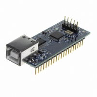
... USB / Microcontroller Module The DLP-245SY-G combines the 4 Parallax SX48 microcontroller to form a rapid development tool. The SX48 microcontroller is preprogrammed with basic functionality for accessing the port pins and can be reprogrammed with user developed firmware via a 5-pin header (4 pins used for compatibility with device programmers and debuggers from other manufacturers). ...
Page 2
... USB bar code readers GENERAL DESCRIPTION The DLP-245SY-G provides a cost-effective, microcontroller-based method of interfacing an electronic peripheral to a host computer via USB. To send data from the peripheral to the host computer, the microcontroller simply writes the byte-wide data into the FT245RL when TXE# is low. If the FT245RL’s transmit buffer fills busy storing the previously written byte, it will take its TXE# high in order to stop further data from being written until some of the FIFO data has been transferred over USB to the host ...
Page 3
... DLP-245SY-G). The latest version of the drivers can be downloaded from dlpdesign.com or ftdichip.com. Once loaded, the VCP drivers allow your application software running on the host PC to communicate with the DLP-245SY-G as though it were connected to a COM (RS-232) port. In addition to VCP drivers, FTDI's D2XX direct drivers for Windows offer an alternative solution to the VCP drivers that allow application software to interface with the DLP-245SY-G using a DLL instead of a virtual com port ...
Page 4
... Note: The board will not operate until a power source has been selected as mentioned in Step 2. 3. Connect the DLP-245SY-G board to the PC via a standard A-B, 6-foot USB cable. This action initiates the loading of the USB drivers. When prompted, select the folder where the DLL version of the device drivers was stored in Step 1 ...
Page 5
... The DLP-245SY-G is shipped with default VID, PID, etc. values programmed into the EEPROM. You only need to run MPROG if you want to change the default values. At this point, the DLP-245SY-G is ready for use. Note that the DLP-245SY-G will appear non-responsive if data sent from the host PC is not read from the FT245RL device by the SX48 microcontroller ...
Page 6
... PIN_E4 0xE4, PIN_E5 0xE5, PIN_E6 0xE6, PIN_E7 0xE7 The source code for the Token I/O firmware (developed for the SnXC C compiler from Grich RC) is available as a free download upon purchase of the DLP-245SY-G. Example Visual C++ source code (for Windows 98/2000/XP) for communicating with the DLP-245SY-G via the Token I/O firmware is also available for download upon purchase ...
Page 7
TOKEN I/O COMMAND SET 0xA5 – Line In – Reads the state of a single port pin Parameters: Port – Select from available port pins (PIN_A3, PIN_B0, etc) Returns: 1 Byte: State of the port pin ( Function: ...
Page 8
EEPROM Write Parameters: Address – Selects the zero-based address of the location in the EEPROM for writing. Data – Data to be written to the EEPROM. Returns: Undefined. Function: This function will write the selected location in the ...
Page 9
In addition to power and ground, a 1.5K to 4.7K pull-up resistor must be connected between VCC and the data pin of the DS18S20 for ...
Page 10
... This function will write the specified data byte to the 8-pit port. Data is latched on the port pins until changed by another command. The port is automatically configured as an output port. Example: 0x2, 0x5C, 0x12, 0xBF – Writes the data byte 0x12 to the 8-bit data bus Port D. TABLE 1: DLP-245SY-G PINOUT DESCRIPTION Pin # Description 1 C0 ...
Page 11
... PORTVCC if the module powered by the USB port (typical configuration). 20 PORTVCC (Out) Power from USB port. Connect to EXTVCC if module powered by the USB port (typical configuration). 500mA is the maximum current available to the DLP-245SY-G and target electronics if the USB device is configured for high power. 21 DB7 (I/O) Line 7 of the data bus between the SX48 and the FT245RL USB-FIFO ...
Page 12
E3 (I/O) Port Pin E3 connected to the SX48 microcontroller (I/O) Port Pin E4 connected to the SX48 microcontroller (I/O) Port Pin E5 connected to the SX48 microcontroller (I/O) Port Pin E6 connected ...
Page 13
... This product and its documentation are supplied on an as-is basis, and no warranty as to their suitability for any particular purpose is either made or implied. DLP Design will not accept any claim for damages whatsoever arising as a result of use or failure of this product. Your statutory rights are not affected ...
Page 14
GND 8 VCC VDD VSS 1 MCLR# 19 VSS 5 VSS 33 VSS 47 VSS 25 AGND 7 GND 18 GND 21 GND 26 TEST VCCIO 18 VDD 4 VDD 32 VDD 46 VDD 4 ...