DLP-IO20 DLP Design Inc, DLP-IO20 Datasheet
DLP-IO20
Specifications of DLP-IO20
DLP-IO20-G
Available stocks


Related parts for DLP-IO20


DLP-IO20 Summary of contents
Page 1
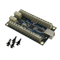
... The 20 channels on the DLP-IO20 are broken down as follows: 3 outputs with high current relay/LED drivers, and 17 Digital I/ which can be set to analog input mode. The DLP-IO20 also provides 2 latching relay contacts. Each of the channels and relay contacts can be controlled via simple multi- byte commands ...
Page 2
... Sink/Source Current on Any I/O: 25mA Sink/Source Current on all I/O combined: 90mA 4.0 WARNINGS • Unplug from the host PC before connecting to the I/O terminals on the DLP-IO20. • Isolate the bottom of the board from all conductive surfaces. • Observe static precautions to prevent damage to the DLP-IO20 module. ...
Page 3
... Right click on the entry under USB Controllers that appears when the DLP-IO20 is connected, select Properties, select the Advanced tab, put a check in the option for “Load VCP” and click OK. Unplug and replug the DLP-IO20 and a COM port should appear in Device Manager under Ports (COM & LPT). ...
Page 4
... IO pin an input. The maximum pull-up voltage is 5.3 volts. 3. Relay contacts can support resistive loads VDC, 0.6A @ 110 VDC, and 125 VAC. If this value is exceeded the DLP-IO20 can be damaged. The relay is set and reset under software control. For a functional schematic of the relay connections refer to figure 8 ...
Page 5
... R1, S1, C1, R2, S2, and C2 are described in table 1. A functional view of how one of the relays works is shown here. Figure 1: Relay Functional Schematic Note: On power up of the DLP-IO20, the relay states will be unknown. Each can power up in either the set or reset state known initial state is required, the user will need to issue either a set or reset command on power up. ...
Page 6
... You can either utilize the TestApp program (described in the following section number 8) provided with the DLP-IO20, or write your own program in your language of choice. Begin by opening the COM port, and send multi-byte commands as shown in Table 2 below. There is no need to set the baud rate because the DLP-IO20 uses a parallel interface between the USB IC and the microcontroller ...
Page 7
... Trigger Event Count on Falling Edge 0x01 Trigger Event Count on Rising Edge Nothing Returned 0 0x03 3 byte packet 1 0x37 Read Event Counter Command 2 0x06 Channel D6 0x07 Channel D7 32 bit count value returned as 4 bytes, with the LS Byte first. 7 © DLP Design, Inc. ...
Page 8
... Read Sensor Command (see Note 3) 2 0x01- Select Channel 0x00-0x13 (See Command 0x39 above) 0x13 2 bytes are returned Byte Temperature Value (see Note Byte of Temperature Value (see Note 5) 0x00 returned for both bytes indicates conversion not complete A successful read initiates another conversion. 8 © DLP Design, Inc. ...
Page 9
... Number of Samples = 2048 conversion. 0x05 Number of Samples = 4096 0x06 Number of Samples = 8192 9 O C), 94mS max convert time O C), 188mS max convert time O C), 375mS max convert time O C), 750mS max Returns data in real time as each A/D conversion completes. 2 bytes are © DLP Design, Inc. ...
Page 10
... The user will need to handle the sign and convert the negative number before translating the binary representation into a decimal temperature value. One example of how to do this is shown in the DLP-IO20 Demo code provided. Other examples are available from Rev ...
Page 11
... DLP-IO20 Figure 3: Digital Temperature Sensor Connection Example To detect a sensor, send the DLP-IO20 the Detect Sensor command (0x39) packet for the appropriate channel. Eight bytes will be returned from this command packet. If the channel is stuck low a 1 will be returned in the first byte sensor is present a 2 will be returned in the first byte. In these two cases, the remaining 7 bytes will be all zeroes ...
Page 12
... Demo Application Program A test application program called IO20Demo is provided with the purchase of the DLP-IO20 that runs on Windows XP / Vista, and can be used to interface with and control the DLP-IO20. Note that the Visual C++ source is also available with the purchase of the DLP-IO20. This application is designed to demonstrate all available features ...
Page 13
... DLP-IO20 12.0 DISCLAIMER © DLP Design, Inc., 2000 - 2009 Neither the whole nor any part of the information contained herein nor the product described in this manual may be adapted or reproduced in any material or electronic form without the prior written consent of the copyright holder ...