DLP-2232M-G DLP Design Inc, DLP-2232M-G Datasheet - Page 11
DLP-2232M-G
Manufacturer Part Number
DLP-2232M-G
Description
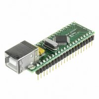
MODULE USB ADAPTER FOR FT2232D
Manufacturer
DLP Design Inc
Datasheet
1.DLP-2232M-G.pdf
(33 pages)
Specifications of DLP-2232M-G
Main Purpose
Interface, USB 2.0 to UART (RS232) Bridge
Embedded
No
Utilized Ic / Part
FT2232D
Primary Attributes
Full Speed USB to High-Speed UART
Secondary Attributes
Royalty-Free Drivers, 2K EEPROM
Interface Type
USB
Data Bus Width
8 bit
Operating Supply Voltage
4.35 V to 5.25 V
Product
Interface Modules
For Use With/related Products
FT2232D
Lead Free Status / RoHS Status
Lead free / RoHS Compliant
Lead Free Status / RoHS Status
Lead free / RoHS Compliant, Lead free / RoHS Compliant
Other names
813-1000


Pin#
13
12
11
10
9
8
7
6
5
4
3
2
1
*Note 2
enabled in the external EEPROM. Enhanced Asynchronous and Synchronous Bit-Bang
modes, MPSSE, and MCU Host Bus Emulation modes are enabled using driver
commands.
*Note 3
Isolated Serial Mode. If both Channel A and Channel B are in Fast Opto-Isolated Serial
Mode all of the IO will be on Channel B.
*Note 4
*Note 5
*Note 6
are on these pins when the main Channel mode is 245 FIFO, CPU FIFO interface, or Fast
Opto-Isolated Serial Modes.
*Note 7
are on these pins when the main Channel mode is 232 UART Mode.
*Note 8
are on these pins when the main Channel mode is 245 FIFO, CPU FIFO interface. Bit-
Bang mode is not available on Channel B when Fast Opto-Isolated Serial Mode is
enabled.
Rev 1.6 (May 2009)
Generic
Pin
Name
BDBUS0
BDBUS1
BDBUS2
BDBUS3
BDBUS4
BDBUS5
BDBUS6
BDBUS7
BCBUS0
BCBUS1
BCBUS2
BCBUS3
SI/WUB
: 232 UART, 245 FIFO, CPU FIFO Interface, and Fast Opto-Isolated modes are
: Channel A can be configured in another IO mode if channel B is in Fast Opto-
: MPSSE is Channel A only.
: MCU Host Bus Emulation requires both Channels.
: The Bit-Bang Mode (synchronous and asynchronous) WR# and RD# strobes
: The Bit-Bang Mode (synchronous and asynchronous) WR# and RD# strobes
: The Bit-Bang Mode (synchronous and asynchronous) WR# and RD# strobes
232 UART
Mode
TXD
RXD
RTS#
CTS#
DTR#
DSR#
DCD#
RI#
TXDEN
SLEEP#
RXLED#
TXLED#
???
245
FIFO
Mode
D0
D1
D2
D3
D4
D5
D6
D7
RXF#
TXE#
RD#
WR
SI/WUB
CPU
FIFO
Interface
Mode
D0
D1
D2
D3
D4
D6
D7
CS#
A0
RD#
WR#
SI/WUB
D5
Pin Definitions by Chip Mode
11
Enhanced
Asynchronous
and
Synchronous
Bit-Bang
Modes
D0
D1
D2
D3
D4
D5
D6
D7
WR#
RD#
WR#
RD#
*Note 8
*Note 7
*Note 8
*Note 7
DLP-2232M-G DLP Design, Inc.
MPSSE
*Note 4
*Note 2
MCU Host
Bus
Enumeration
Mode
*Note 5
AD8
AD9
AD10
AD11
AD12
AD13
AD14
AD15
CS#
ALE
RD#
WR#
Fast
Opto-
Isolated
Serial
Mode
FSDI
FSCLK
FSDO
FSCTS
*Note 3
Related parts for DLP-2232M-G
Image
Part Number
Description
Manufacturer
Datasheet
Request
R

Part Number:
Description:
MODULE USB-TO-TTL PARL FIFO CONV
Manufacturer:
DLP Design Inc
Datasheet:

Part Number:
Description:
KIT DEV DLP LIGHTCOMANDER
Manufacturer:
Logic
Datasheet:

Part Number:
Description:
MODULE DATA-ACQUISITION 8-CH
Manufacturer:
DLP Design Inc
Datasheet:

Part Number:
Description:
MODULE DATA-ACQUISITION 20-CH
Manufacturer:
DLP Design Inc
Datasheet:

Part Number:
Description:
RFID READER/WRITER SNGL-CH OEM
Manufacturer:
DLP Design Inc
Datasheet:

Part Number:
Description:
Interface Modules & Development Tools DLP-245PL PACKAGED w/CCS Compiler
Manufacturer:
DLP Design Inc

Part Number:
Description:
Interface Modules & Development Tools DLP-245PB-G BOARD + CCS Compiler
Manufacturer:
DLP Design Inc
Datasheet:

Part Number:
Description:
Interface Modules & Development Tools DLP-TILT SENSOR ACCEL VIBRATION
Manufacturer:
DLP Design Inc

Part Number:
Description:
MODULE USB-MCU FT245RL W/16F877A
Manufacturer:
DLP Design Inc
Datasheet:

Part Number:
Description:
MODULE USB-TO-FPGA TRAINING TOOL
Manufacturer:
DLP Design Inc
Datasheet:

Part Number:
Description:
MODULE USB-MCU FT232R W/18F2410
Manufacturer:
DLP Design Inc
Datasheet:

Part Number:
Description:
MODULE USB-MCU FT245RL W/SX48
Manufacturer:
DLP Design Inc
Datasheet:

Part Number:
Description:
MODULE USB-MCU FT2232D W/16F877A
Manufacturer:
DLP Design Inc
Datasheet:

Part Number:
Description:
MODULE USB-TO-FPGA SPARTAN3
Manufacturer:
DLP Design Inc
Datasheet:

Part Number:
Description:
MOD USB-MCU FT245RL W/18LF8722
Manufacturer:
DLP Design Inc
Datasheet: