NCP5331FTR2G ON Semiconductor, NCP5331FTR2G Datasheet - Page 36
NCP5331FTR2G
Manufacturer Part Number
NCP5331FTR2G
Description
IC CTLR PWM 2PH W/DRVRS 32-LQFP
Manufacturer
ON Semiconductor
Datasheet
1.NCP5331FTR2G.pdf
(36 pages)
Specifications of NCP5331FTR2G
Applications
Controller, AMD Athlon™
Voltage - Input
9 ~ 14 V
Number Of Outputs
2
Voltage - Output
5V
Operating Temperature
0°C ~ 70°C
Mounting Type
Surface Mount
Package / Case
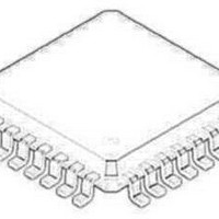
32-LQFP
Mounting Style
SMD/SMT
Lead Free Status / RoHS Status
Lead free / RoHS Compliant
Other names
NCP5331FTR2G
NCP5331FTR2GOSTR
NCP5331FTR2GOSTR
Available stocks
Company
Part Number
Manufacturer
Quantity
Price
Company:

Part Number:
NCP5331FTR2G
Manufacturer:
ON Semiconductor
Quantity:
10 000
Part Number:
NCP5331FTR2G
Manufacturer:
ON/安森美
Quantity:
20 000


PUBLICATION ORDERING INFORMATION
V
AMD Athlon is a trademark of Advanced Micro Devices, Inc.
LITERATURE FULFILLMENT:
Literature Distribution Center for ON Semiconductor
P.O. Box 61312, Phoenix, Arizona 85082−1312 USA
Phone: 480−829−7710 or 800−344−3860 Toll Free USA/Canada
Fax: 480−829−7709 or 800−344−3867 Toll Free USA/Canada
Email: orderlit@onsemi.com
SEATING
2
ON Semiconductor and
to any products herein. SCILLC makes no warranty, representation or guarantee regarding the suitability of its products for any particular purpose, nor does SCILLC assume any liability
arising out of the application or use of any product or circuit, and specifically disclaims any and all liability, including without limitation special, consequential or incidental damages.
“Typical” parameters which may be provided in SCILLC data sheets and/or specifications can and do vary in different applications and actual performance may vary over time. All
operating parameters, including “Typicals” must be validated for each customer application by customer’s technical experts. SCILLC does not convey any license under its patent rights
nor the rights of others. SCILLC products are not designed, intended, or authorized for use as components in systems intended for surgical implant into the body, or other applications
intended to support or sustain life, or for any other application in which the failure of the SCILLC product could create a situation where personal injury or death may occur. Should
Buyer purchase or use SCILLC products for any such unintended or unauthorized application, Buyer shall indemnify and hold SCILLC and its officers, employees, subsidiaries, affiliates,
and distributors harmless against all claims, costs, damages, and expenses, and reasonable attorney fees arising out of, directly or indirectly, any claim of personal injury or death
associated with such unintended or unauthorized use, even if such claim alleges that SCILLC was negligent regarding the design or manufacture of the part. SCILLC is an Equal
Opportunity/Affirmative Action Employer. This literature is subject to all applicable copyright laws and is not for resale in any manner.
PLANE
is a trademark of Switch Power, Inc.
C
9
B
E
−AB−
−AC−
B1
−T−
H
8X
8
1
M_
W
DETAIL AD
32
9
S1
are registered trademarks of Semiconductor Components Industries, LLC (SCILLC). SCILLC reserves the right to make changes without further notice
A1
G
A
S
0.10 (0.004) AC
DETAIL Y
X
−Z−
K
25
R
4X
Q_
17
4X
0.20 (0.008)
−U−
N. American Technical Support: 800−282−9855 Toll Free
USA/Canada
Japan: ON Semiconductor, Japan Customer Focus Center
0.20 (0.008)
2−9−1 Kamimeguro, Meguro−ku, Tokyo, Japan 153−0051
Phone: 81−3−5773−3850
V1
PACKAGE DIMENSIONS
DETAIL AD
V
http://onsemi.com
CASE 873A−02
AB
FT SUFFIX
NCP5331
AC
LQFP−32
ISSUE B
T−U
P
T−U
36
Z
SECTION AE−AE
Z
F
É É
É É
É É
METAL
BASE
J
N
DETAIL Y
D
AE
AE
ON Semiconductor Website: http://onsemi.com
Order Literature: http://www.onsemi.com/litorder
For additional information, please contact your
local Sales Representative.
NOTES:
1. DIMENSIONING AND TOLERANCING
2. CONTROLLING DIMENSION:
3. DATUM PLANE −AB− IS LOCATED AT
4. DATUMS −T−, −U−, AND −Z− TO BE
5. DIMENSIONS S AND V TO BE
6. DIMENSIONS A AND B DO NOT INCLUDE
7. DIMENSION D DOES NOT INCLUDE
8. MINIMUM SOLDER PLATE THICKNESS
9. EXACT SHAPE OF EACH CORNER MAY
PER ANSI Y14.5M, 1982.
MILLIMETER.
BOTTOM OF LEAD AND IS COINCIDENT
WITH THE LEAD WHERE THE LEAD
EXITS THE PLASTIC BODY AT THE
BOTTOM OF THE PARTING LINE.
DETERMINED AT DATUM PLANE −AB−.
DETERMINED AT SEATING PLANE −AC−.
MOLD PROTRUSION. ALLOWABLE
PROTRUSION IS 0.250 (0.010) PER SIDE.
DIMENSIONS A AND B DO INCLUDE
MOLD MISMATCH AND ARE
DETERMINED AT DATUM PLANE −AB−.
DAMBAR PROTRUSION. DAMBAR
PROTRUSION SHALL NOT CAUSE THE
D DIMENSION TO EXCEED 0.520 (0.020).
SHALL BE 0.0076 (0.0003).
VARY FROM DEPICTION.
DIM
A1
B1
S1
V1
W
A
B
C
D
E
G
H
K
M
N
P
Q
R
S
V
X
F
J
1.400
0.300
1.350
0.300
0.050
0.090
0.500
0.090
0.150
MILLIMETERS
MIN
7.000 BSC
3.500 BSC
7.000 BSC
3.500 BSC
0.800 BSC
0.400 BSC
9.000 BSC
4.500 BSC
9.000 BSC
4.500 BSC
0.200 REF
1.000 REF
12 REF
1
_
_
1.600
0.450
1.450
0.400
0.150
0.200
0.700
0.160
0.250
MAX
5
_
0.055
0.012
0.053
0.012
0.002
0.004
0.020
0.004
0.006
MIN
NCP5331/D
0.276 BSC
0.138 BSC
0.276 BSC
0.138 BSC
0.031 BSC
0.016 BSC
0.354 BSC
0.177 BSC
0.354 BSC
0.177 BSC
0.008 REF
0.039 REF
1
12 REF
INCHES
_
_
0.063
0.018
0.057
0.016
0.006
0.008
0.028
0.006
0.010
MAX
5
_
Related parts for NCP5331FTR2G
Image
Part Number
Description
Manufacturer
Datasheet
Request
R

Part Number:
Description:
Two-Phase PWM Controller with Integrated Gate Drivers
Manufacturer:
ON Semiconductor
Datasheet:
Part Number:
Description:
ON Semiconductor [VOLTAGE REGULATOR]
Manufacturer:
ON Semiconductor
Datasheet:
Part Number:
Description:
357-036-542-201 CARDEDGE 36POS DL .156 BLK LOPRO
Manufacturer:
ON Semiconductor
Datasheet:
Part Number:
Description:
357-036-542-201 CARDEDGE 36POS DL .156 BLK LOPRO
Manufacturer:
ON Semiconductor
Datasheet:
Part Number:
Description:
357-036-542-201 CARDEDGE 36POS DL .156 BLK LOPRO
Manufacturer:
ON Semiconductor
Datasheet:
Part Number:
Description:
357-036-542-201 CARDEDGE 36POS DL .156 BLK LOPRO
Manufacturer:
ON Semiconductor
Datasheet:
Part Number:
Description:
357-036-542-201 CARDEDGE 36POS DL .156 BLK LOPRO
Manufacturer:
ON Semiconductor
Datasheet:
Part Number:
Description:
357-036-542-201 CARDEDGE 36POS DL .156 BLK LOPRO
Manufacturer:
ON Semiconductor
Datasheet:
Part Number:
Description:
357-036-542-201 CARDEDGE 36POS DL .156 BLK LOPRO
Manufacturer:
ON Semiconductor
Datasheet:
Part Number:
Description:
357-036-542-201 CARDEDGE 36POS DL .156 BLK LOPRO
Manufacturer:
ON Semiconductor
Datasheet:
Part Number:
Description:
357-036-542-201 CARDEDGE 36POS DL .156 BLK LOPRO
Manufacturer:
ON Semiconductor
Datasheet:
Part Number:
Description:
357-036-542-201 CARDEDGE 36POS DL .156 BLK LOPRO
Manufacturer:
ON Semiconductor
Datasheet:
Part Number:
Description:
Manufacturer:
ON Semiconductor
Datasheet:
Part Number:
Description:
Manufacturer:
ON Semiconductor
Datasheet: