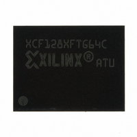
XCF128XFTG64C Xilinx Inc, XCF128XFTG64C Datasheet - Page 42

XCF128XFTG64C
Manufacturer Part Number
XCF128XFTG64C
Description
IC PROM SRL 128M GATE 64-FTBGA
Manufacturer
Xilinx Inc
Datasheet
1.XCF128XFTG64C.pdf
(88 pages)
Specifications of XCF128XFTG64C
Memory Size
128Mb
Programmable Type
In System Programmable
Voltage - Supply
1.7 V ~ 2 V
Operating Temperature
-40°C ~ 85°C
Package / Case
64-TBGA
Access Time
85ns
Supply Voltage Range
1.7V To 2V
Memory Case Style
FTBGA
No. Of Pins
64
Operating Temperature Range
-40°C To +85°C
Svhc
No SVHC (15-Dec-2010)
Package /
RoHS Compliant
Lead Free Status / RoHS Status
Lead free / RoHS Compliant
Other names
122-1578
Available stocks
Company
Part Number
Manufacturer
Quantity
Price
Company:
Part Number:
XCF128XFTG64C
Manufacturer:
XILINX
Quantity:
319
Part Number:
XCF128XFTG64C
Manufacturer:
XILINX/赛灵思
Quantity:
20 000
Program and Erase Times and Endurance Cycles
Table 21
depending on the memory array condition. The best case is when all the bits in the block are at ‘0’ (pre-programmed). The
worst case is when all the bits in the block are at ‘1’ (not preprogrammed). Usually, the system overhead is negligible with
respect to the erase time. The maximum number of program/erase cycles depends on the V
Table 21: Program/Erase Times and Endurance Cycles
DS617 (v3.0.1) January 07, 2010
Product Specification
Notes:
1.
2.
3.
4.
T
Values are liable to change with the external system-level overhead (command sequence and Status Register polling execution).
Excludes the time needed to execute the command sequence.
This is an average value on the entire device.
A
= –25°C to 85 °C; V
Parameter
lists both program and erase times plus the number of program/erase cycles per block. Exact erase times can vary
Program/Erase
Program/Erase
Blank Check
R
Cycles (per
Cycles (per
Program
Program
Suspend
Latency
Block)
Block)
Erase
Erase
(3)
(3)
DD
= 1.7V to 2V; V
Buffer (32 words)
Main Block (64
Main Block (64
Bank (8 Mbits)
Single Word
Single Word
Buffer (32 words) (Buffer Program)
Kwords)
Kword)
Parameter Block (16 Kword)
Parameter Block (16 Kword)
Main Block (64 Kword)
Main Block (64 Kword)
Parameter Blocks
Parameter Blocks
Parameter Blocks
DDQ
Main Blocks
Main Blocks
Main Blocks
Condition
Program
= 2.3V to 2.7V or 3.0V to 3.6V.
Erase
Not Preprogrammed
Factory Program
Buffer Enhanced
Buffer Enhanced
Factory Program
Buffer Enhanced
Factory Program
Buffer Enhanced
Factory Program
Preprogrammed
Buffer Program
Buffer Program
Buffer Program
Buffer Program
Word Program
Word Program
Platform Flash XL High-Density Configuration and Storage Device
www.xilinx.com
(1,2)
(4)
10,000
10,000
Min
–
–
–
–
–
–
–
–
–
–
–
–
–
–
–
–
–
–
–
–
–
–
–
1.28
1.28
Typ
384
768
160
160
0.4
1.2
1.5
0.4
2.5
12
12
10
80
80
16
5
5
1
4
–
–
–
–
Typical after 10k
P/E Cycles
PP
1
3
–
–
–
–
–
–
–
–
–
–
–
–
–
–
–
–
–
–
–
–
–
–
–
voltage supply used.
2500
1000
Max
180
170
180
2.5
2.5
10
25
4
4
–
–
–
–
4
–
–
–
–
–
–
–
–
–
cycles
cycles
cycles
cycles
Unit
ms
ms
ms
ms
ms
μs
μs
μs
μs
μs
μs
μs
μs
μs
s
s
s
s
s
s
s
42


