MT46H16M16LFBF-6 IT:A Micron Technology Inc, MT46H16M16LFBF-6 IT:A Datasheet - Page 63
MT46H16M16LFBF-6 IT:A
Manufacturer Part Number
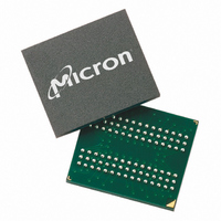
MT46H16M16LFBF-6 IT:A
Description
IC DDR SDRAM 256MBIT 60VFBGA
Manufacturer
Micron Technology Inc
Type
DDR SDRAMr
Specifications of MT46H16M16LFBF-6 IT:A
Format - Memory
RAM
Memory Type
Mobile DDR SDRAM
Memory Size
256M (16Mx16)
Speed
166MHz
Interface
Parallel
Voltage - Supply
1.7 V ~ 1.95 V
Operating Temperature
-40°C ~ 85°C
Package / Case
60-VFBGA
Organization
16Mx16
Density
256Mb
Address Bus
15b
Access Time (max)
6.5/5ns
Maximum Clock Rate
166MHz
Operating Supply Voltage (typ)
1.8V
Package Type
VFBGA
Operating Temp Range
-40C to 85C
Operating Supply Voltage (max)
1.95V
Operating Supply Voltage (min)
1.7V
Supply Current
100mA
Pin Count
60
Mounting
Surface Mount
Operating Temperature Classification
Industrial
Lead Free Status / Rohs Status
Compliant
Other names
Q3368612


Notes
PDF: 09005aef82091978 / Source: 09005aef8209195b
MT46H16M16LF__2.fm - Rev. H 6/08 EN
10. Enables on-chip refresh and address counters.
11. Fast command/address input slew rate ≥1 V/ns. Slow command/address input slew
12.
13. The maximum limit for this parameter is not a device limit. The device will operate
14. This is not a device limit. The device will operate with a negative value, but system
15. It is recommended that DQS be valid (HIGH or LOW) on or before the WRITE com-
2. All parameters assume proper device initialization.
3. Tests for AC timing, I
4. Outputs measured with equivalent load; transmission line delay is assumed to be very
5. Timing and I
6. All AC timings assume an input slew rate of 1V/ns.
7. V
8. The value of V
9. I
1. All voltages referenced to V
at nominal supply voltage levels, but the related specifications and device operation
are guaranteed for the full voltage range specified.
small:
but input timing is still referenced to V
The output timing reference voltage level is V
level on CK#.
track variations in the DC level of the same.
with minimum cycle time at CL = 3 for -6 and CL = 3 for -75 with the outputs open.
rate ≥0.5 V/ns. If the slew rate is less than 0.5 V/ns, timing must be derated:
additional 50ps per each 100 mV/ns reduction in slew rate from the 0.5 V/ns.
remains constant. If the slew rate exceeds 4.5 V/ns, functionality is uncertain.
t
tions. These parameters are not referenced to a specific voltage level but specify when
the device output is no longer driving (HZ) or begins driving (LZ).
with a greater value for this parameter, but system performance (bus turnaround) will
degrade accordingly.
performance (bus turnaround) will degrade accordingly.
mand. The case shown (DQS going from High-Z to logic LOW) applies when no
WRITEs were previously in progress on the bus. If a previous WRITE was in progress,
DQS could be HIGH during this time, depending on
I/O
I/O
DD
HZ and
One-half-drive strength
ID
Full-drive strength
is the magnitude of the difference between the input level on CK and the input
is dependent on output loading and cycle rates. Specified values are obtained
Z
Z
0
0
= 50
= 50
t
LZ transitions occur in the same access time windows as data valid transi-
DD
IX
tests may use a V
is expected to equal V
20pF
10pF
DD
, and electrical AC and DC characteristics may be conducted
63
SS
.
One-eighth-drive strength
I/O
I/O
IL
-to-V
Quarter-drive strength
Micron Technology, Inc., reserves the right to change products or specifications without notice.
256Mb: x16, x32 Mobile DDR SDRAM
Z
Z
DD
DD
0
0
IH
= 50
= 50
Q/2 of the transmitting device and must
Q/2 (or to the crossing point for CK/CK#).
swing of up to 1.5V in the test environment,
DD
Q/2.
5pF
2.5pF
t
DQSS.
©2005 Micron Technology, Inc. All rights reserved.
t
IS has an
t
IH
Notes
Related parts for MT46H16M16LFBF-6 IT:A
Image
Part Number
Description
Manufacturer
Datasheet
Request
R

Part Number:
Description:
IC SDRAM 64MBIT 133MHZ 54TSOP
Manufacturer:
Micron Technology Inc
Datasheet:

Part Number:
Description:
IC SDRAM 64MBIT 5.5NS 86TSOP
Manufacturer:
Micron Technology Inc
Datasheet:
Part Number:
Description:
IC SDRAM 64MBIT 200MHZ 86TSOP
Manufacturer:
Micron Technology Inc
Datasheet:
Part Number:
Description:
IC SDRAM 64MBIT 133MHZ 54TSOP
Manufacturer:
Micron Technology Inc
Datasheet:
Part Number:
Description:
IC SDRAM 128MBIT 133MHZ 54TSOP
Manufacturer:
Micron Technology Inc
Datasheet:

Part Number:
Description:
IC SDRAM 256MBIT 133MHZ 90VFBGA
Manufacturer:
Micron Technology Inc
Datasheet:
Part Number:
Description:
IC SDRAM 128MBIT 133MHZ 54TSOP
Manufacturer:
Micron Technology Inc
Datasheet:
Part Number:
Description:
IC SDRAM 256MBIT 133MHZ 54TSOP
Manufacturer:
Micron Technology Inc
Datasheet:

Part Number:
Description:
IC DDR SDRAM 512MBIT 6NS 66TSOP
Manufacturer:
Micron Technology Inc
Datasheet:
Part Number:
Description:
IC SDRAM 128MBIT 167MHZ 86TSOP
Manufacturer:
Micron Technology Inc
Datasheet:
Part Number:
Description:
IC SDRAM 128MBIT 143MHZ 86TSOP
Manufacturer:
Micron Technology Inc
Datasheet:

Part Number:
Description:
SDRAM 256M-BIT 1.8V 54-PIN VFBGA
Manufacturer:
Micron Technology Inc
Datasheet:
Part Number:
Description:
IC SDRAM 128MBIT 143MHZ 86TSOP
Manufacturer:
Micron Technology Inc
Datasheet:

Part Number:
Description:
IC SDRAM 128MBIT 125MHZ 54VFBGA
Manufacturer:
Micron Technology Inc
Datasheet:
Part Number:
Description:
IC SDRAM 128MBIT 125MHZ 54VFBGA
Manufacturer:
Micron Technology Inc
Datasheet: