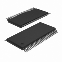
SC28L202A1DGG/G,11 NXP Semiconductors, SC28L202A1DGG/G,11 Datasheet - Page 23

SC28L202A1DGG/G,11
Manufacturer Part Number
SC28L202A1DGG/G,11
Description
IC UART DUAL W/FIFO 56-TSSOP
Manufacturer
NXP Semiconductors
Series
IMPACTr
Datasheet
1.SC28L202A1DGG118.pdf
(77 pages)
Specifications of SC28L202A1DGG/G,11
Features
False-start Bit Detection
Number Of Channels
2, DUART
Fifo's
256 Byte
Voltage - Supply
3.3V, 5V
With Parallel Port
Yes
With Auto Flow Control
Yes
With False Start Bit Detection
Yes
With Modem Control
Yes
With Cmos
Yes
Mounting Type
Surface Mount
Package / Case
56-TFSOP (0.240", 6.10mm Width)
Lead Free Status / RoHS Status
Lead free / RoHS Compliant
Other names
935279792118
SC28L202A1DGG/G-T
SC28L202A1DGG/G-T
SC28L202A1DGG/G-T
SC28L202A1DGG/G-T
Philips Semiconductors
last character sent the Xon/Xoff logic would not automatically send
the negating Xon.
The kill CRTX command (of the command register) can be used to
cleanly terminate any pending CRTX commands.
NOTE: In no case will a Xon/Xoff character transmission be aborted.
Once the character is loaded into the TX Shift Register, transmission
continues until completion or a chip reset or transmitter reset is
encountered. The kill CRTX command has no effect in either of the
Auto modes.
Xon/Xoff Interrupts
The Xon/Xoff logic generates interrupts only in response to
recognizing either of the characters in the XonCR or XoffCR (Xon or
Xoff Character Registers). The transmitter activity initiated by the
Xon/Xoff logic or any CR command does not generate an interrupt.
The character comparators operate regardless of the value in
MR3[3:2]. Hence the comparators may be used as general-purpose
character detectors by setting MR3[3:2]= ‘00’ and enabling the
Xon/Xoff interrupt in the IMR.
The Dual UART can present the Xon/Xoff recognition event to the
interrupt arbiter for IRQN generation. The IRQN generation may be
masked by setting bit 4 of the Interrupt Mask Register, IMR. The bid
level of a Xon/Xoff recognition event is controlled by the Bidding
Control Register X, BCRx, of the channel. The interrupt status can
be examined in ISR[4]. If cleared, no Xon/Xoff recognition event is
interrupting. If set, a Xon or Xoff recognition event has been
detected. The X Interrupt Status Register, XISR, can be read for
details of the interrupt and to examine other, non-interrupting, status
of the Xon/Xoff logic. Refer to the XISR in the Register Descriptions.
The character recognition function and the associated interrupt
generation is disabled on hardware or software reset.
Multi-drop or Wake up or 9 bit mode
This mode is used to address a particular UART among a group
connected to the same serial data source. Normally it is
accomplished by redefining the meaning of the parity bit such that it
indicates a character as address or data. While this method is fully
supported in the SC28L202 it also supports recognition of the
character itself. Upon recognition of its address the receiver will be
enabled and data loaded onto the RxFIFO.
Further the Address recognition has the ability, if so programmed, to
disable (not reset) the receiver when an address is seen that is not
recognized as its own. The particular features of ‘Auto Wake and
Auto Doze’ are described in the detail descriptions under ‘Receiver
Operation’ above.
2005 Nov 01
Dual UART
17
NOTE: Care should be taken in the programming of the character
recognition registers. Programming x’00, for example, may result in
a break condition being recognized as a control character. This will
be further complicated when binary data is being processed.
PROGRAMMING THE HOST INTERFACE
The SC28L202 is designed for a very close compatibility with legacy
software written for other Philips/Signetics 2 channel UARTs. The
part will initialize to the SC28L92 function. This function is controlled
in the low 16 address positions.
A reset (both hardware and software) will return the part to this
mode with the control registers set for 9600 baud, 8 bits, no parity
and one stop bit. Interrupt will be set for Receiver Ready and
transmitter Empty. Transmitters and receivers will not be enabled.
Basic operation should be obtained by a single write of 0xE0 to the
command register. That will enable the receiver and transmitter.
Addressing outside of the lower 16 address spaces will enable all
the advanced features. In general, before calling legacy code,
advanced features should be disabled (character stripping, for
example).
Writing control words into the appropriate registers programs the
operation of the DUART. Operational feedback is provided via status
registers that can be read by the CPU. The addressing of the
registers is described in the Register Map.
The contents of certain control registers are initialized to zero on
RESET. Care should be exercised if the contents of a register are
changed during operation, since certain changes may cause
operational problems.
For example, changing the number of bits per character while the
transmitter is active may cause the transmission of an incorrect
character. In general, the contents of the MR, the CSR, and the
OPCR should only be changed while the receiver(s) and
transmitter(s) are not enabled, and certain changes to the ACR
should only be made while the C/T is stopped.
Each channel has 3 mode registers (MR0, 1, 2) which control the
basic configuration of the channel. Mode, command, clock select,
and status registers are duplicated for each channel to provide total
independent operation and control. Refer to Table 2 for register bit
descriptions.
SC28L202
Product data sheet


