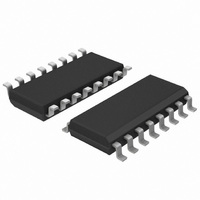
UJA1023T/2R04,512 NXP Semiconductors, UJA1023T/2R04,512 Datasheet - Page 26

UJA1023T/2R04,512
Manufacturer Part Number
UJA1023T/2R04,512
Description
IC CAN/LIN I/O SLAVE 32HTSSOP
Manufacturer
NXP Semiconductors
Datasheet
1.UJA1023T2R04C51.pdf
(49 pages)
Specifications of UJA1023T/2R04,512
Applications
LIN Controller
Interface
LIN (Local Interconnect Network)
Voltage - Supply
6.5 V ~ 27 V
Package / Case
16-SOIC (3.9mm Width)
Mounting Type
Surface Mount
Lead Free Status / RoHS Status
Lead free / RoHS Compliant
Other names
935281302512
UJA1023T/2R04
UJA1023T/2R04
UJA1023T/2R04
UJA1023T/2R04
NXP Semiconductors
UJA1023
Product data sheet
7.2.2.5 Limp home mode and Standby mode
7.2.3.1 Input
7.2.3.2 Level mode
7.2.3.3 PWM mode
7.2.3.4 Cyclic sense mode
7.2.3 I/O pin modes
In LH sleep mode the PWM and ADC are reset. The first LIN message will be lost due to
waking up the UJA1023.
Limp home mode and Standby mode differ in the output of pin INH if the INH is configured
in External regulator mode. Where in Limp home mode pin INH is high-impedance and in
Standby mode pin INH is HIGH. In contrast to the Standby mode the Limp home mode is
a low-power mode.
The limp home value specifies the PxOut values in case LIN bus communication fails. The
Px configuration push-pull, open-drain or high-impedance keeps unchanged in Limp
home mode.
The Limp home mode will be entered from Normal mode if the LIN bus is short-circuited to
ground for a time exceeding the bus dominant time-out (t
(t
Coming from Limp home mode the Standby mode is entered after remote wake-up if the
UJA1023 is configured. In case the UJA1023 is not configured, it enters the Configuration
mode after remote wake-up.
In Standby and Configuration mode the UJA1023 enters the Limp home mode again if the
configuration fails or if the ‘Sleep mode command’ has been received.
Inputs can always be read via a PxResp frame (see
determined by the TH bits in the second I/O configuration block (see
In Level mode the PxOut register of the UJA1023 can be set or reset. Depending on the
Px configuration the PxOut value is output.
The PWM mode provides a PWM signal with 8-bit resolution to the I/O-stage. The base
frequency is typically 700 kHz divided by 256 (8-bit) and becomes approximately 2.7 kHz.
The mode is entered via both mode configuration bits OM0 and OM1. The PWM signal is
common for all assigned outputs.
In the low-power modes (Sleep mode, LH sleep mode and Limp home mode) the PWM
value is reset (PWM = 0x00) and the previous PWM value is lost.
The Cyclic sense mode is used to supply and read back external switches. In this mode
the Px pin is configured as a switched supply to reduce the power consumption. It is
primarily intended to supply wake-up switches.
A Px pin in Cyclic sense mode has to be configured with the High-Side Enable register
(HSE) in HIGH-state and the Low-Side Enable register (LSE) in LOW-state. The PxOut
flip-flop is being cyclically switched (see
to(idle)
) expires.
All information provided in this document is subject to legal disclaimers.
Rev. 5 — 17 August 2010
Figure
7).
Section
to(dom)
7.2.5). The input threshold is
) or if the bus idle time-out
Table
UJA1023
© NXP B.V. 2010. All rights reserved.
17).
LIN-I/O slave
26 of 49


