ADF4002BCPZ Analog Devices Inc, ADF4002BCPZ Datasheet - Page 3
ADF4002BCPZ
Manufacturer Part Number
ADF4002BCPZ
Description
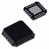
IC PLL FREQUENCY SYNTH 20-LFCSP
Manufacturer
Analog Devices Inc
Type
Clock/Frequency Synthesizer (RF), Phase Detectorr
Datasheet
1.ADF4002BCPZ.pdf
(20 pages)
Specifications of ADF4002BCPZ
Design Resources
Very Low Jitter Encode (Sampling) Clocks for High Speed Analog-to-Digital Converters Using ADF4002 (CN0003)
Pll
Yes
Input
CMOS
Output
Clock
Number Of Circuits
1
Ratio - Input:output
2:1
Differential - Input:output
Yes/No
Frequency - Max
400MHz
Divider/multiplier
Yes/No
Voltage - Supply
2.7 V ~ 3.3 V
Operating Temperature
-40°C ~ 85°C
Mounting Type
Surface Mount
Package / Case
20-LFCSP
Frequency-max
400MHz
Pll Type
Frequency Synthesis
Frequency
400MHz
Supply Current
5mA
Supply Voltage Range
2.7V To 3.3V
Digital Ic Case Style
LFCSP
No. Of Pins
20
Operating Temperature Range
-40°C To +85°C
Lead Free Status / RoHS Status
Lead free / RoHS Compliant
For Use With
EVAL-ADF4002EBZ1 - BOARD EVAL FOR ADF4002
Lead Free Status / RoHS Status
Lead free / RoHS Compliant, Lead free / RoHS Compliant
Available stocks
Company
Part Number
Manufacturer
Quantity
Price
Company:

Part Number:
ADF4002BCPZ
Manufacturer:
MICREL
Quantity:
115
Part Number:
ADF4002BCPZ
Manufacturer:
ADI/亚德诺
Quantity:
20 000
Company:
Part Number:
ADF4002BCPZ-RL7
Manufacturer:
ADI
Quantity:
1 497
Part Number:
ADF4002BCPZ-RL7
Manufacturer:
ADI/亚德诺
Quantity:
20 000


SPECIFICATIONS
AV
T
Table 1.
Parameter
RF CHARACTERISTICS
REFIN CHARACTERISTICS
PHASE DETECTOR
CHARGE PUMP
LOGIC INPUTS
LOGIC OUTPUTS
POWER SUPPLIES
NOISE CHARACTERISTICS
1
2
3
4
5
6
Operating temperature range (B version) is −40°C to +85°C.
AV
AC coupling ensures AV
Guaranteed by design. Sample tested to ensure compliance.
T
frequency in MHz.
The normalized phase noise floor is estimated by measuring the in-band phase noise at the output of the VCO and subtracting 20logN (where N is the N divider value)
and 10logF
EVAL-ADF4002EB1 and the HP8644B as the PLL reference.
A
A
RF Input Sensitivity
RF Input Frequency (RF
REFIN Input Frequency
REFIN Input Sensitivity
REFIN Input Capacitance
REFIN Input Current
Phase Detector Frequency
I
I
I
Sink and Source Current Matching
I
V
V
I
C
V
V
I
V
AV
DV
V
I
I
Power-Down Mode
Normalized Phase Noise Floor
CP
CP
CP
CP
INH
OH
DD
P
DD
= T
= 25°C; AV
DD
IH
IL
IN
OH
OH
OL
P
, Input Low Voltage
High Value
Low Value
Absolute Accuracy
R
Three-State Leakage
, Input High Voltage
DD
5
Sink/Source
vs. V
vs. Temperature
, Input Capacitance
, I
DD
= DV
, Output Low Voltage
, Output High Voltage
, Output High Voltage
= DV
SET
(AI
MAX
INL
, Input Current
Range
DD
CP
DD
PFD
to T
= 3 V.
DD
+ DI
DD
. PN
= DV
= 3 V ± 10%, AV
MIN
SYNTH
DD
, unless otherwise noted.
)
DD
= PN
= 3 V; RF
DD
/2 bias.
TOT
2
IN
− 10logF
)
IN
= 350 MHz. The current for any other setup (25°C, 3.0 V) in mA is given by 2.35 + 0.0046 (REFIN) + 0.0062 (RF), RF frequency and REFIN
4
DD
6
PFD
≤ V
− 20logN. All phase noise measurements were performed with an Agilent E5500 phase noise test system, using the
P
≤ 5.5 V, AGND = DGND = CPGND = 0 V, R
Min
−10
5
20
0.8
3.0
1.4
1.4
V
2.7
AV
AV
DD
DD
DD
− 0.4
B Version
Typ
5
625
2.5
1
1.5
2
2
5.0
1
−222
1
Max
0
400
300
V
10
±100
104
11
0.6
±1
10
100
0.4
3.3
5.5
6.0
0.4
Rev. A | Page 3 of 20
DD
Unit
dBm
MHz
MHz
V p-p
pF
μA
MHz
mA
μA
%
kΩ
nA
%
%
%
V
V
μA
pF
V
V
μA
V
V
V
mA
mA
μA
dBc/Hz
Test Conditions/Comments
See Figure 11 for input circuit
For RF
For REFIN < 20 MHz, ensure SR > 50 V/μs
Biased at AV
ABP = 0, 0 (2.9 ns antibacklash pulse width)
Programmable, see Figure 18
With R
With R
See Figure 18
T
0.5 V ≤ V
0.5 V ≤ V
V
Open-drain output chosen, 1 kΩ pull-up resistor to 1.8 V
CMOS output chosen
I
AV
T
AI
OL
A
A
CP
DD
= 25°C
DD
= 25°C
= 500 μA
SET
= V
+ DI
≤ V
IN
= 5.1 kΩ, dBm referred to 50 Ω,
SET
SET
P
/2
< 5 MHz, ensure slew rate (SR) > 4 V/μs
P
CP
CP
DD
= 5.1 kΩ
= 5.1 kΩ
≤ 5.5 V
≤ V
≤ V
DD
P
P
/2
− 0.5 V
− 0.5 V
3
ADF4002
Related parts for ADF4002BCPZ
Image
Part Number
Description
Manufacturer
Datasheet
Request
R

Part Number:
Description:
±1.7g Dual-Axis IMEMS Accelerometer Evaluation Board
Manufacturer:
Analog Devices Inc
Datasheet:

Part Number:
Description:
Inertial Sensor Evaluation System
Manufacturer:
Analog Devices Inc
Datasheet:
Part Number:
Description:
Manufacturer:
Analog Devices Inc
Datasheet:
Part Number:
Description:
Manufacturer:
Analog Devices Inc
Datasheet:
Part Number:
Description:
Manufacturer:
Analog Devices Inc
Datasheet:
Part Number:
Description:
Manufacturer:
Analog Devices Inc
Datasheet:
Part Number:
Description:
Manufacturer:
Analog Devices Inc
Datasheet:
Part Number:
Description:
Manufacturer:
Analog Devices Inc
Datasheet:
Part Number:
Description:
Manufacturer:
Analog Devices Inc
Datasheet:
Part Number:
Description:
Manufacturer:
Analog Devices Inc
Datasheet:
Part Number:
Description:
Manufacturer:
Analog Devices Inc
Datasheet:
Part Number:
Description:
Manufacturer:
Analog Devices Inc
Datasheet:
Part Number:
Description:
Manufacturer:
Analog Devices Inc
Datasheet: