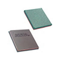
EP1S30F1020C5N Altera, EP1S30F1020C5N Datasheet - Page 272

EP1S30F1020C5N
Manufacturer Part Number
EP1S30F1020C5N
Description
Stratix
Manufacturer
Altera
Datasheet
1.EP1S30F1020C5N.pdf
(276 pages)
Specifications of EP1S30F1020C5N
Family Name
Stratix
Number Of Logic Blocks/elements
32470
# I/os (max)
726
Frequency (max)
500MHz
Process Technology
0.13um (CMOS)
Operating Supply Voltage (typ)
1.5V
Logic Cells
32470
Ram Bits
3317184
Operating Supply Voltage (min)
1.425V
Operating Supply Voltage (max)
1.575V
Operating Temp Range
0C to 85C
Operating Temperature Classification
Commercial
Mounting
Surface Mount
Pin Count
1020
Package Type
FC-FBGA
Lead Free Status / Rohs Status
Compliant
Available stocks
Company
Part Number
Manufacturer
Quantity
Price
Company:
Part Number:
EP1S30F1020C5N
Manufacturer:
ALTERA
Quantity:
455
Part Number:
EP1S30F1020C5N
Manufacturer:
ALTERA/阿尔特拉
Quantity:
20 000
- Current page: 272 of 276
- Download datasheet (4Mb)
DLL Specifications
DLL
Specifications
4–102
Stratix Device Handbook, Volume 1
Notes to
(1)
(2)
(3)
(4)
(5)
(6)
(7)
(8)
t
ARESET
Table 4–133. Fast PLL Specifications for -8 Speed Grades (Part 2 of 2)
Symbol
See
PLLs 7, 8, 9, and 10 in the EP1S80 device support up to 717-MHz input and output.
Use this equation (f
ranges to determine the allowed PLL settings.
When using the SERDES, high-speed differential I/O mode supports a maximum output frequency of 210 MHz
to the global or regional clocks (that is, the maximum data rate 840 Mbps divided by the smallest SERDES J factor
of 4).
Refer to the section
This parameter is for high-speed differential I/O mode only.
These counters have a maximum of 32 if programmed for 50/50 duty cycle. Otherwise, they have a maximum
of 16.
High-speed differential I/O mode supports W = 1 to 16 and J = 4, 7, 8, or 10.
“Maximum Input & Output Clock Rates” on page
Tables 4–131
f
Minimum pulse width on
signal
through 4–133:
O U T
“High-Speed I/O Specification” on page 4–87
= f
Table 4–134
circuit.
For more information on DLL jitter, see the DDR SRAM section in the
Stratix Architecture chapter of the Stratix Device Handbook, Volume 1.
Table 4–135
across all PVT conditions. The Stratix DLL can be used below these
frequencies, but it will not achieve the full phase shift requested across all
I N
Parameter
Table 4–134. DLL Jitter for DQS Phase Shift Reference Circuit
* ml(n × post-scale counter)) in conjunction with the specified f
Frequency (MHz)
areset
reports the jitter for the DLL in the DQS phase shift reference
lists the Stratix DLL low frequency limit for full phase shift
197 to 200
160 to 196
100 to 159
4–76.
Min
10
for more information.
Max
DLL Jitter (ps)
± 100
± 300
± 500
Altera Corporation
I N P F D
January 2006
and f
V C O
Unit
ns
Related parts for EP1S30F1020C5N
Image
Part Number
Description
Manufacturer
Datasheet
Request
R

Part Number:
Description:
CYCLONE II STARTER KIT EP2C20N
Manufacturer:
Altera
Datasheet:

Part Number:
Description:
CPLD, EP610 Family, ECMOS Process, 300 Gates, 16 Macro Cells, 16 Reg., 16 User I/Os, 5V Supply, 35 Speed Grade, 24DIP
Manufacturer:
Altera Corporation
Datasheet:

Part Number:
Description:
CPLD, EP610 Family, ECMOS Process, 300 Gates, 16 Macro Cells, 16 Reg., 16 User I/Os, 5V Supply, 15 Speed Grade, 24DIP
Manufacturer:
Altera Corporation
Datasheet:

Part Number:
Description:
Manufacturer:
Altera Corporation
Datasheet:

Part Number:
Description:
CPLD, EP610 Family, ECMOS Process, 300 Gates, 16 Macro Cells, 16 Reg., 16 User I/Os, 5V Supply, 30 Speed Grade, 24DIP
Manufacturer:
Altera Corporation
Datasheet:

Part Number:
Description:
High-performance, low-power erasable programmable logic devices with 8 macrocells, 10ns
Manufacturer:
Altera Corporation
Datasheet:

Part Number:
Description:
High-performance, low-power erasable programmable logic devices with 8 macrocells, 7ns
Manufacturer:
Altera Corporation
Datasheet:

Part Number:
Description:
Classic EPLD
Manufacturer:
Altera Corporation
Datasheet:

Part Number:
Description:
High-performance, low-power erasable programmable logic devices with 8 macrocells, 10ns
Manufacturer:
Altera Corporation
Datasheet:

Part Number:
Description:
Manufacturer:
Altera Corporation
Datasheet:

Part Number:
Description:
Manufacturer:
Altera Corporation
Datasheet:

Part Number:
Description:
Manufacturer:
Altera Corporation
Datasheet:

Part Number:
Description:
CPLD, EP610 Family, ECMOS Process, 300 Gates, 16 Macro Cells, 16 Reg., 16 User I/Os, 5V Supply, 25 Speed Grade, 24DIP
Manufacturer:
Altera Corporation
Datasheet:


