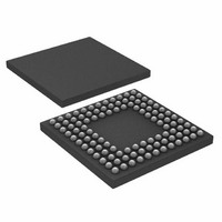
ADUC7121BBCZ-RL Analog Devices Inc, ADUC7121BBCZ-RL Datasheet - Page 88

ADUC7121BBCZ-RL
Manufacturer Part Number
ADUC7121BBCZ-RL
Description
PRECISION ANALOG MCU I.C
Manufacturer
Analog Devices Inc
Series
MicroConverter® ADuC7xxxr
Datasheet
1.ADUC7121BBCZ.pdf
(96 pages)
Specifications of ADUC7121BBCZ-RL
Core Processor
ARM7
Core Size
16/32-Bit
Speed
41.78MHz
Connectivity
I²C, SPI, UART/USART
Peripherals
POR, PWM, WDT
Number Of I /o
32
Program Memory Size
126KB (63K x 16)
Program Memory Type
FLASH
Ram Size
8K x 8
Voltage - Supply (vcc/vdd)
3 V ~ 3.6 V
Data Converters
A/D 9x12b, D/A 4x12b
Oscillator Type
Internal
Operating Temperature
-10°C ~ 95°C
Package / Case
108-LFBGA, CSPBGA
Lead Free Status / RoHS Status
Lead free / RoHS Compliant
Eeprom Size
-
Lead Free Status / RoHS Status
Lead free / RoHS Compliant
Other names
ADUC7121BBCZ-RL
ADUC7121BBCZ-RLTR
ADUC7121BBCZ-RLTR
Available stocks
Company
Part Number
Manufacturer
Quantity
Price
Company:
Part Number:
ADUC7121BBCZ-RL
Manufacturer:
Analog Devices Inc
Quantity:
10 000
ADuC7121
Timer0 Capture Register
This is a 16-bit register that holds the 16-bit value captured by
an enabled IRQ event; available in 16-bit mode only.
Name:
Address:
Default value:
Access:
Timer0 Control Register
This 17-bit MMR configures the mode of operation of Timer0.
Name:
Address:
Default value:
Access:
Table 123. T0CON MMR Bit Designations
Bit
31:18
17
16:12
11
10:9
8
7
6
5
4
Value
00
01
10
11
0
1
T0CAP
0xFFFF0314
0x0000
Read only
T0CON
0xFFFF030C
0x00000000
Read and write
Description
Reserved.
Event select bit.
Set by the user to enable time capture of an
event.
Cleared by the user to disable time capture of
an event.
Event select range, 0 to 16. The events are
described in the introduction to the Timers
section.
Reserved.
Clock select.
Internal 32 kHz oscillator.
UCLK.
External 32 kHz crystal.
HCLK.
Count up. Available in 16-bit mode only.
Set by the user for Timer0 to count up.
Cleared by the user for Timer0 to count down
(default).
Timer0 enable bit.
Set by the user to enable Timer0.
Cleared by the user to disable Timer0
(default).
Timer0 mode.
Set by the user to operate in periodic mode.
Cleared by the user to operate in free-running
mode (default).
Reserved.
Timer0 mode of operation.
16-bit operation (default).
48-bit operation.
Rev. 0 | Page 88 of 96
Bit
3:0
Timer0 Load Registers
T0LD is a 16-bit register that holds the 16-bit value that is
loaded into the counter; available only in 16-bit mode.
Name:
Address:
Default value:
Access:
Timer0 Clear Register
This 8-bit, write-only MMR is written (with any value) by user
code to refresh (reload) Timer0.
Name:
Address:
Default value:
Access:
TIMER1—GENERAL-PURPOSE TIMER
Timer1 is a 32-bit general-purpose timer, count down or count
up, with a programmable prescaler. The prescaler source can be
from the 32 kHz internal oscillator, the 32 kHz external crystal,
the core clock, or from the undivided PLL clock output. This
source can be scaled by a factor of 1, 16, 256, or 32,768. This gives
a minimum resolution of 22 ns when operating at CD zero, the
core is operating at 41.78 MHz, and with a prescaler of one.
The counter can be formatted as a standard 32-bit value or as
hours:minutes:seconds:hundreths.
Timer1 has a capture register (T1CAP) that can be triggered by
a source initial assertion of a selected IRQ. When triggered, the
current timer value is copied to T1CAP, and the timer keeps
running. This feature can be used to determine the assertion of
an event with increased accuracy. Timer1 interface consists of
five MMRs as shown in Table 124.
If the part is in a low power mode and Timer1 is clocked from
the GPIO or low power oscillator source, then Timer1
continues to operate.
Timer1 reloads the value from T1LD either when Timer1
overflows or immediately when T1ICLR is written.
Value
0000
0100
1000
1111
T0LD
0xFFFF0300
0x00
Read and write
T0CLRI
0xFFFF0310
0x00
Write only
Description
Prescaler.
Source clock divide-by-1 (default).
Source clock divide-by-16.
Source clock divide-by-256.
Source clock divide-by-32,768.


