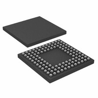
ADUC7121BBCZ-RL Analog Devices Inc, ADUC7121BBCZ-RL Datasheet - Page 34

ADUC7121BBCZ-RL
Manufacturer Part Number
ADUC7121BBCZ-RL
Description
PRECISION ANALOG MCU I.C
Manufacturer
Analog Devices Inc
Series
MicroConverter® ADuC7xxxr
Datasheet
1.ADUC7121BBCZ.pdf
(96 pages)
Specifications of ADUC7121BBCZ-RL
Core Processor
ARM7
Core Size
16/32-Bit
Speed
41.78MHz
Connectivity
I²C, SPI, UART/USART
Peripherals
POR, PWM, WDT
Number Of I /o
32
Program Memory Size
126KB (63K x 16)
Program Memory Type
FLASH
Ram Size
8K x 8
Voltage - Supply (vcc/vdd)
3 V ~ 3.6 V
Data Converters
A/D 9x12b, D/A 4x12b
Oscillator Type
Internal
Operating Temperature
-10°C ~ 95°C
Package / Case
108-LFBGA, CSPBGA
Lead Free Status / RoHS Status
Lead free / RoHS Compliant
Eeprom Size
-
Lead Free Status / RoHS Status
Lead free / RoHS Compliant
Other names
ADUC7121BBCZ-RL
ADUC7121BBCZ-RLTR
ADUC7121BBCZ-RLTR
Available stocks
Company
Part Number
Manufacturer
Quantity
Price
Company:
Part Number:
ADUC7121BBCZ-RL
Manufacturer:
Analog Devices Inc
Quantity:
10 000
ADuC7121
POWER SUPPLY MONITOR
The power supply monitor on the ADuC7121 indicates when
the IOVDD supply pin drops below one of two supply trip
points. The monitor function is controlled via the PSMCON
register. If enabled in the IRQEN or FIQEN register, the monitor
interrupts the core using the PSMI bit in the PSMCON MMR.
This bit is cleared immediately after CMP goes high. Note that
if the interrupt generated is exited before CMP goes high
(IOVDD supply voltage is above the trip point), no further
Table 40. PSMCON MMR Bit Designations (Address = 0xFFFF0440, Default Value = 0x0008)
Bit
15:4
3
2
1
0
Name
Reserved
CMP
TP
PSMEN
PSMI
Description
These bits are reserved.
Comparator bit. This is a read-only bit that directly reflects the state of the comparator.
Read 1 indicates that the IOVDD supply is above its selected trip point or the PSM is in power-down mode.
Read 0 indicates the IOVDD supply is below its selected trip point. Set this bit before leaving the interrupt
service routine.
Trip point selection bit.
0 = 2.79 V.
1 = 3.07 V.
Power supply monitor enable bit.
Set to 1 by the user to enable the power supply monitor circuit.
Cleared to 0 by the user to disable the power supply monitor circuit.
Power supply monitor interrupt bit. This bit is set high by the MicroConverter if CMP is low, indicating low
I/O supply. The PSMI bit can be used to interrupt the processor. When CMP returns high, the PSMI bit can
be cleared by writing a 1 to this location. A write of 0 has no effect. There is no timeout delay. PSMI can be
cleared immediately after CMP goes high.
Rev. 0 | Page 34 of 96
interrupts are generated until CMP returns high. The user
needs to ensure that the code execution remains within the ISR
until CMP returns high.
This monitor function allows the user to save working registers
to avoid possible data loss due to low supply or brownout con-
ditions. It also ensures that normal code execution does not
resume until a safe supply level has been established.
The PSM does not operate correctly when using JTAG debug;
therefore, disable PSM while in JTAG debug mode.


