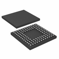
ADUC7121BBCZ-RL Analog Devices Inc, ADUC7121BBCZ-RL Datasheet - Page 66

ADUC7121BBCZ-RL
Manufacturer Part Number
ADUC7121BBCZ-RL
Description
PRECISION ANALOG MCU I.C
Manufacturer
Analog Devices Inc
Series
MicroConverter® ADuC7xxxr
Datasheet
1.ADUC7121BBCZ.pdf
(96 pages)
Specifications of ADUC7121BBCZ-RL
Core Processor
ARM7
Core Size
16/32-Bit
Speed
41.78MHz
Connectivity
I²C, SPI, UART/USART
Peripherals
POR, PWM, WDT
Number Of I /o
32
Program Memory Size
126KB (63K x 16)
Program Memory Type
FLASH
Ram Size
8K x 8
Voltage - Supply (vcc/vdd)
3 V ~ 3.6 V
Data Converters
A/D 9x12b, D/A 4x12b
Oscillator Type
Internal
Operating Temperature
-10°C ~ 95°C
Package / Case
108-LFBGA, CSPBGA
Lead Free Status / RoHS Status
Lead free / RoHS Compliant
Eeprom Size
-
Lead Free Status / RoHS Status
Lead free / RoHS Compliant
Other names
ADUC7121BBCZ-RL
ADUC7121BBCZ-RLTR
ADUC7121BBCZ-RLTR
Available stocks
Company
Part Number
Manufacturer
Quantity
Price
Company:
Part Number:
ADUC7121BBCZ-RL
Manufacturer:
Analog Devices Inc
Quantity:
10 000
ADuC7121
I
This 8-bit MMR is the I
Name:
Address:
Default value:
Access:
I
This 8-bit MMR is the I
Name:
Address:
Default value:
Access:
I
This 16-bit MMR holds the required number of bytes when the
master begins a read sequence from a slave device.
Name:
Address:
Default value:
Access:
Table 89. I2CxMCNT0 MMR Bit Descriptions
Bit
15:9
8
7:0
I
This 8-bit MMR holds the number of bytes received so far
during a read sequence with a slave device.
Name:
Address:
Default value:
Access:
2
2
2
2
C Master Receive Registers
C Master Transmit Registers
C Master Read Count Registers
C Master Current Read Count Registers
Name
I2CRECNT
I2CRCNT
I2C0MRX, I2C1MRX
0xFFFF0888, 0xFFFF0908
0x00
Read only
I2C0MTX, I2C1MTX
0xFFFF088C, 0xFFFF090C
0x00
Write only
I2C0MCNT0, I2C1MCNT0
0xFFFF0890, 0xFFFF0910
0x0000
Read and write
I2C0MCNT1, I2C1MCNT1
0xFFFF0894, 0xFFFF0914
0x00
Read only
Description
Reserved.
Set this bit if greater than 256 bytes are
required from the slave.
Clear this bit when reading 256 bytes or less.
These 8 bits hold the number of bytes
required during a slave read sequence,
minus 1. If only a single byte is required, set
these bits to 0.
2
2
C master receive register.
C master transmit register.
Rev. 0 | Page 66 of 96
I
This 8-bit MMR holds the 7-bit slave address + the read/ write
bit when the master begins communicating with a slave.
Name:
Address:
Default value:
Access:
Table 90. I2CxADR0 MMR in 7-Bit Address Mode
Bit
7:1
0
Table 91. I2CxADR0 MMR in 10-Bit Address Mode
Bit
7:3
2:1
0
I
This 8-bit MMR is used in 10-bit addressing mode only. This
register contains the least significant byte of the address.
Name:
Address:
Default value:
Access:
Table 92. I2CxADR1 MMR in 10-Bit Address Mode
Bit
7:0
2
2
C Address 0 Registers
C Address 1 Register
Name
I2CADR
R/ W
Name
I2CMADR
R/ W
Name
I2CLADR
I2C0ADR0, I2C1ADR0
0xFFFF0898, 0xFFFF0918
0x00
Read and write
I2C0ADR1, I2C1ADR1
0xFFFF089C, 0xFFFF091C
0x00
Read and write
Description
These bits contain ADDR[7:0] in 10-bit
addressing mode.
Description
These bits contain the 7-bit address of the
required slave device.
Bit 0 is the read/ write bit.
When this bit = 1, a read sequence is
requested.
When this bit = 0, a write sequence is
requested.
Description
These bits must be set to [11110b] in 10-bit
address mode.
These bits contain ADDR[9:8] in 10-bit
addressing mode.
Read/ write bit.
When this bit = 1, a read sequence is
requested.
When this bit = 0, a write sequence is
requested.


