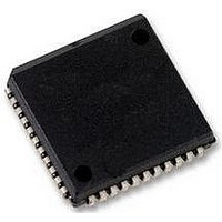
SC28L92A1A NXP Semiconductors, SC28L92A1A Datasheet - Page 35

SC28L92A1A
Manufacturer Part Number
SC28L92A1A
Description
UART, DUAL, 3.3V OR 5V, SMD, 28L92
Manufacturer
NXP Semiconductors
Datasheet
1.SC28L92A1B557.pdf
(73 pages)
Specifications of SC28L92A1A
No. Of Channels
2
Supply Voltage Range
2.97V To 3.63V, 4.5V To 5.5V
Operating Temperature Range
-40°C To +85°C
Digital Ic Case Style
PLCC
No. Of Pins
44
Svhc
No SVHC (18-Jun-2010)
Operating
RoHS Compliant
Data Rate
230.4Kilobaud
Uart Features
Programmable Channel Mode, Line Break Detection & Generation
Rohs Compliant
Yes
Available stocks
Company
Part Number
Manufacturer
Quantity
Price
Company:
Part Number:
SC28L92A1A
Manufacturer:
NXP
Quantity:
677
Company:
Part Number:
SC28L92A1A,512
Manufacturer:
NXP Semiconductors
Quantity:
10 000
Company:
Part Number:
SC28L92A1A,518
Manufacturer:
NXP Semiconductors
Quantity:
10 000
Company:
Part Number:
SC28L92A1A,529
Manufacturer:
NXP Semiconductors
Quantity:
10 000
Company:
Part Number:
SC28L92A1A529
Manufacturer:
NXP Semiconductors
Quantity:
135
NXP Semiconductors
SC28L92_7
Product data sheet
7.3.3.1 Command Register channel A (CRA)
7.3.3 Command registers
Table 38.
CRA is a register used to supply commands to channel A. Multiple commands can be
specified in a single write to CRA as long as the commands are non-conflicting, e.g., the
enable transmitter and reset transmitter commands cannot be specified in a single
command word.
Table 39.
Table 40.
Bit
7 to 4
3
2
1
0
Command
0000
0001
0010
0011
0100
0101
7
Symbol
-
-
-
-
-
channel command code
CRA - Command register channel A (address 0x2) and
CRB - Command register channel B (address 0xA) bit allocation
CRA - Command register channel A (address 0x2) bit description
Miscellaneous commands
Description
No command.
Reset MR pointer. Causes the channel A MR pointer to point to MR1.
Reset receiver. Resets the channel A receiver as if a hardware reset had been
applied. The receiver is disabled and the FIFO is flushed.
Reset transmitter. Resets the channel A transmitter as if a hardware reset had
been applied.
Reset error status. Clears the channel A received break, parity error, and overrun
error bits in the status register (SRA[7:4]). Used in character mode to clear OE
status (although RB, PE and FE bits will also be cleared) and in block mode to clear
all error status after a block of data has been received.
Reset channel A break change interrupt. Causes the channel A break detect
change bit in the interrupt status register (ISR[2]) to be cleared to zero.
6
Description
Miscellaneous commands. Execution of the commands in the upper four bits
of this register must be separated by 3 X1 clock edges. Other reads or writes
(including writes to the lower four bits) may be inserted to achieve this
separation. A description of miscellaneous commands is given in
Disable channel A transmitter. This command terminates transmitter operation
and reset the TxDRY and TxEMT status bits. However, if a character is being
transmitted or if a character is in the Tx FIFO when the transmitter is disabled,
the transmission of the character(s) is completed before assuming the inactive
state.
Enable channel A transmitter. Enables operation of the channel A transmitter.
The TxRDY and TxEMT status bits will be asserted if the transmitter is idle.
Disable channel A receiver. This command terminates operation of the
receiver immediately-a character being received will be lost. The command
has no effect on the receiver status bits or any other control registers. If the
special multi-drop mode is programmed, the receiver operates even if it is
disabled. See
Enable channel A receiver. Enables operation of the channel A receiver. If not
in the special wake-up mode, this also forces the receiver into the search for
start-bit state.
Rev. 07 — 19 December 2007
3.3 V/5.0 V Dual Universal Asynchronous Receiver/Transmitter
5
Section
4
6.3.10.
disable Tx
3
enable Tx
2
disable Rx
SC28L92
© NXP B.V. 2007. All rights reserved.
1
Table
enable Rx
35 of 73
0
40.


