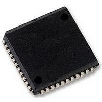
SC28L92A1A NXP Semiconductors, SC28L92A1A Datasheet - Page 16

SC28L92A1A
Manufacturer Part Number
SC28L92A1A
Description
UART, DUAL, 3.3V OR 5V, SMD, 28L92
Manufacturer
NXP Semiconductors
Datasheet
1.SC28L92A1B557.pdf
(73 pages)
Specifications of SC28L92A1A
No. Of Channels
2
Supply Voltage Range
2.97V To 3.63V, 4.5V To 5.5V
Operating Temperature Range
-40°C To +85°C
Digital Ic Case Style
PLCC
No. Of Pins
44
Svhc
No SVHC (18-Jun-2010)
Operating
RoHS Compliant
Data Rate
230.4Kilobaud
Uart Features
Programmable Channel Mode, Line Break Detection & Generation
Rohs Compliant
Yes
Available stocks
Company
Part Number
Manufacturer
Quantity
Price
Company:
Part Number:
SC28L92A1A
Manufacturer:
NXP
Quantity:
677
Company:
Part Number:
SC28L92A1A,512
Manufacturer:
NXP Semiconductors
Quantity:
10 000
Company:
Part Number:
SC28L92A1A,518
Manufacturer:
NXP Semiconductors
Quantity:
10 000
Company:
Part Number:
SC28L92A1A,529
Manufacturer:
NXP Semiconductors
Quantity:
10 000
Company:
Part Number:
SC28L92A1A529
Manufacturer:
NXP Semiconductors
Quantity:
135
NXP Semiconductors
SC28L92_7
Product data sheet
6.2.5 Counter mode
6.2.6 Time-out mode
Often this division will result in a non-integer number; 26.3 for example. One may only
program integer numbers to a digital divider. Therefore 26 (0x1A) would be chosen. If 26.7
were the result of the division, then 27 (0x1B) would be chosen. This gives a baud rate
error of 0.3/26.3 or 0.3/26.7 that yields a percentage error of 1.14 % or 1.12 %
respectively, well within the ability of the asynchronous mode of operation. Higher input
frequency to the counter reduces the error effect of the fractional division.
In the counter mode the counter/timer counts the value of the CTLR CTUR down to zero
and then sets the ISR[3] bit and sets the counter/timer output from 1 to 0. It then rolls over
to 65,365 and continues counting with no further observable effect. Reading the C/T in the
counter mode outputs the present state of the C/T. If the C/T is not stopped, a read of the
C/T may result in changing data on the data bus.
The time-out mode uses the received data stream to control the counter. The time-out
mode forces the C/T into the timer mode. Each time a received character is transferred
from the shift register to the Rx FIFO, the counter is restarted. If a new character is not
received before the counter reaches zero count, the counter ready bit is set, and an
interrupt can be generated. This mode can be used to indicate when data has been left in
the Rx FIFO for more than the programmed time limit. If the receiver has been
programmed to interrupt the CPU when the receive FIFO is full, and the message ends
before the FIFO is full, the CPU will not be interrupted for the remaining characters in the
Rx FIFO.
By programming the C/T such that it would time-out in just over one character time, the
above situation could be avoided. The processor would be interrupted any time the data
stream had stopped for more than one character time. Note: This is very similar to the
watchdog time of MR0. The difference is in the programmability of the delay time and that
the watchdog timer is restarted by either a receiver load to the Rx FIFO or a system read
from it.
This mode is enabled by writing the appropriate command to the command register.
Writing 0xA to CRA or CRB will invoke the time-out mode for that channel. Writing 0xC to
CRA or CRB will disable the time-out mode. Only one receiver should use this mode at a
time. However, if both are on, the time-out occurs after both receivers have been inactive
for the time-out period. The start of the C/T will be on the logic OR of the two receivers.
The time-out mode disables the regular start counter or stop counter commands and puts
the C/T into counter mode under the control of the received data stream. Each time a
received character is transferred from the shift register to the Rx FIFO, the C/T is stopped
after one C/T clock, reloaded with the value in CTUR and CTLR and then restarted on the
next C/T clock. If the C/T is allowed to end the count before a new character has been
received, the counter ready bit, ISR[3], will be set. If IMR[3] is set, this will generate an
interrupt. Since receiving a character restarts the C/T, the receipt of a character after the
C/T has timed out will clear the counter ready bit, ISR[3], and the interrupt. Invoking the
Set Time-out Mode On command, CRx = 0xA, will also clear the counter ready bit and
stop the counter until the next character is received. The counter/timer is controlled with
six commands: Start/Stop C/T, Read/Write Counter/Timer lower register and Read/Write
n
=
--------------------------------------------------------------------------
2 16
counter/timer input clock
desired baud rate
Rev. 07 — 19 December 2007
3.3 V/5.0 V Dual Universal Asynchronous Receiver/Transmitter
SC28L92
© NXP B.V. 2007. All rights reserved.
16 of 73
(1)


