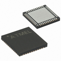
ATMEGA64RZAV-10MU Atmel, ATMEGA64RZAV-10MU Datasheet - Page 52

ATMEGA64RZAV-10MU
Manufacturer Part Number
ATMEGA64RZAV-10MU
Description
MCU ATMEGA644/AT86RF230 44-QFN
Manufacturer
Atmel
Series
ATMEGAr
Datasheets
1.ATMEGA644-20MU.pdf
(23 pages)
2.ATMEGA644-20MU.pdf
(376 pages)
3.AT86RF230-ZU.pdf
(98 pages)
Specifications of ATMEGA64RZAV-10MU
Frequency
2.4GHz
Modulation Or Protocol
802.15.4 Zigbee
Power - Output
3dBm
Sensitivity
-101dBm
Voltage - Supply
1.8 V ~ 3.6 V
Data Interface
PCB, Surface Mount
Memory Size
64kB Flash, 2kB EEPROM, 4kB RAM
Antenna Connector
PCB, Surface Mount
Package / Case
44-VFQFN Exposed Pad
Wireless Frequency
2.4 GHz
Interface Type
JTAG, SPI
Output Power
3 dBm
For Use With
ATSTK600-TQFP32 - STK600 SOCKET/ADAPTER 32-TQFP770-1005 - ISP 4PORT FOR ATMEL AVR MCU JTAG770-1004 - ISP 4PORT FOR ATMEL AVR MCU SPIATAVRISP2 - PROGRAMMER AVR IN SYSTEMATJTAGICE2 - AVR ON-CHIP D-BUG SYSTEMATSTK500 - PROGRAMMER AVR STARTER KIT
Lead Free Status / RoHS Status
Lead free / RoHS Compliant
Operating Temperature
-
Applications
-
Data Rate - Maximum
-
Current - Transmitting
-
Current - Receiving
-
Lead Free Status / Rohs Status
Lead free / RoHS Compliant
For Use With/related Products
ATmega64
8.4.1 Overview
8.4.2 Reading RSSI
8.4.3 Data Interpretation
8.4.4 Register Description
52
AT86RF230
Bit
0x06
Read/Write
Reset value
Bit
0x06
Read/Write
Reset value
The RSSI is a 5-bit value indicating the receive power in the selected channel, in steps
of 3 dB. No attempt is made to distinguish between IEEE 802.15.4 signal and other
signal source, only the received signal power is evaluated. The RSSI provides the basis
for ED measurement.
Using the Basic Operating Mode, the RSSI value is valid at any RX state, and is
updated every 2 μs. The current RSSI value is stored to the PHY_RSSI register.
Note, it is not recommended to read the RSSI value when using the Extended
Operating Mode. The automatically generated ED value should be used alternatively
(see section 8.3).
The PHY_RSSI is an 8-bit register, however, the value is represented in the lowest five
bits [4:0] and the range is 0 – 28.
An RSSI value of 0 indicates an RF input power of < -91 dBm. For an RSSI value in the
range of 1 to 28, the RF input power can be calculated as follows:
Register 0x06 (PHY_RSSI)
The PHY_RSSI register is a multi purpose register to indicate the current received
signal strength (RSSI) and the FCS validity of a received frame.
• Bit 7 – RX_CRC_VALID
Refer to section 8.2.5.
• Bit [6:5] – Reserved
• Bit [4:0] – RSSI
The register bits RSSI contain the result of the automated RSSI measurement. The
value is updated every 2 μs in receive states.
The read value is a number between 0 and 28 indicating the received signal strength as
a linear curve on a logarithmic input power scale (dBm) with a resolution of 3 dB. An
RSSI value of 0 indicates an RF input power of < -91 dBm (see parameter 11.7.17), a
value of 28 a power of ≥ -10 dBm (see parameter 11.7.18).
P
RF
RX_CRC_VALID
= RSSI_BASE_VAL + 3•(RSSI - 1)
R
R
7
0
3
0
R
R
6
0
2
0
Reserved
RSSI
R
R
5
0
1
0
RSSI
R
R
4
0
0
0
5131E-MCU Wireless-02/09
PHY_RSSI
PHY_RSSI


